CYLINDER HEAD GASKET REMOVAL
PROCEDURE
-
REMOVE ENGINE ASSEMBLY
-
REMOVE NO. 1 EXHAUST MANIFOLD HEAT INSULATOR
-
REMOVE NO. 4 INTAKE PIPE
-
REMOVE AIR SWITCHING VALVE ASSEMBLY
-
REMOVE EXHAUST MANIFOLD
-
REMOVE HEATER HOSE
-
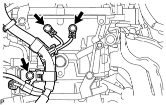
REMOVE VENTILATION PIPE
-
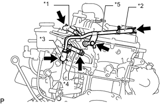
Text in Illustration *1 No. 1 Water By-pass Hose *2 No. 1 Ventilation Hose *3 No. 3 Ventilation Hose *4 No. 3 Water By-pass Hose *5 Ventilation Pipe Slide the clip and disconnect the No. 1 water by-pass hose from throttle body with motor assembly.
-
Slide the clip and disconnect the No. 1 ventilation hose from the PCV valve sub-assembly.
-
Slide the clip and disconnect the No. 3 ventilation hose from the ventilation pipe.
-
Slide the clip and disconnect the No. 3 water by-pass hose from the cylinder head sub-assembly.
-
Remove the bolt and ventilation pipe.
-
-
REMOVE TIMING CHAIN COVER SUB-ASSEMBLY
-
REMOVE CYLINDER HEAD COVER CONNECTOR SUB-ASSEMBLY
-
REMOVE TIMING CHAIN GUIDE
-
SET NO. 1 CYLINDER TO TDC/COMPRESSION
-
REMOVE NO. 1 CHAIN TENSIONER ASSEMBLY
-
REMOVE CHAIN TENSIONER SLIPPER
-
REMOVE NO. 1 CHAIN VIBRATION DAMPER
-
REMOVE CHAIN SUB-ASSEMBLY
-
REMOVE CAMSHAFT BEARING CAP
-
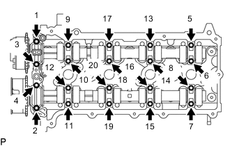
Uniformly loosen and remove the 20 bearing cap bolts in the sequence shown in the illustration.
Note
Uniformly loosen the bolts while keeping the camshaft level.
-
Remove the 9 bearing caps.
Tech Tips
Arrange the removed parts in the correct order.
-
-
REMOVE CAMSHAFT
-
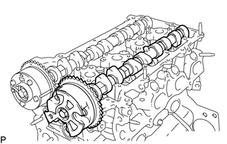
Remove the camshaft.
-
-
REMOVE NO. 2 CAMSHAFT
-
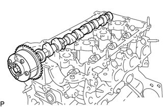
Remove the No. 2 camshaft.
-
-
REMOVE NO. 1 VALVE ROCKER ARM SUB-ASSEMBLY
-
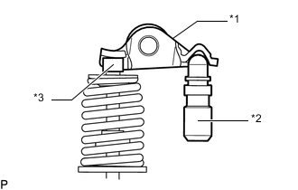
Text in Illustration *1 No. 1 Valve Rocker Arm Sub-assembly *2 Valve Lash Adjuster Assembly *3 Valve Stem Cap Remove the 16 No. 1 valve rocker arm sub-assemblies from the cylinder head sub-assembly.
Tech Tips
Arrange the removed parts in the correct order.
-
-
REMOVE VALVE LASH ADJUSTER ASSEMBLY
-
Remove the 16 valve lash adjuster assemblies from the cylinder head sub-assembly.
Tech Tips
Arrange the removed parts in the correct order.
-
-
REMOVE VALVE STEM CAP
-
Remove the 16 valve stem caps from the cylinder head sub-assembly.
Tech Tips
Arrange the removed parts in the correct order.
-
-
DISCONNECT ENGINE WIRE
-
Remove the 3 bolts and disconnect the engine wire from the cylinder head sub-assembly.
-
-
REMOVE CYLINDER HEAD SUB-ASSEMBLY
-
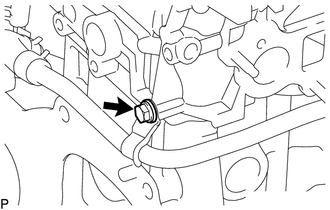
w/ Oil Cooler:
Remove the bolt and disconnect the No. 4 water by-pass pipe.
-
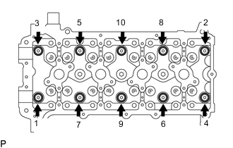
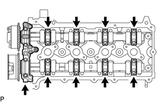
Uniformly loosen the 10 cylinder head set bolts in the sequence shown in the illustration. Remove the 10 cylinder head set bolts and plate washers.
Note
-
Be careful not to drop plate washers into the cylinder head sub-assembly.
-
Head warpage or cracking could result from removing cylinder head set bolts in the incorrect order.
-
-
Remove the cylinder head sub-assembly.
-
-
REMOVE CYLINDER HEAD GASKET
-
Remove the cylinder head gasket from the cylinder block.
-
-
INSPECT CYLINDER HEAD SET BOLT
-
INSPECT CYLINDER HEAD SUB-ASSEMBLY