WATER PUMP REMOVAL
PROCEDURE
-
DISCONNECT CABLE FROM NEGATIVE BATTERY TERMINAL
Note
-
After turning the ignition switch off, waiting time may be required before disconnecting the cable from the battery terminal. Therefore, make sure to read the disconnecting the cable from the battery terminal notice before proceeding with work Click here.
-
When disconnecting the cable, some systems need to be initialized after the cable is reconnected Click here.
-
-
REMOVE UPPER RADIATOR SUPPORT SEAL
-
REMOVE FRONT BUMPER LOWER COVER
-
REMOVE NO. 1 ENGINE UNDER COVER SUB-ASSEMBLY
-
REMOVE ENGINE REAR UNDER COVER ASSEMBLY
-
DRAIN ENGINE COOLANT
-
REMOVE ELECTRIC EGR CONTROL VALVE ASSEMBLY (w/ EGR System)
-
Remove the electric EGR control valve assembly Click here.
-
-
DISCONNECT INLET HEATER WATER HOSE (w/o EGR System)
-
DISCONNECT NO. 4 VACUUM TRANSMITTING PIPE SUB-ASSEMBLY (w/o EGR System)
-
REMOVE NO. 1 INTAKE PIPE (w/o EGR System)
-
REMOVE THROTTLE BODY BRACKET (w/o EGR System)
-
REMOVE NO. 1, NO. 2 AND NO. 3 INJECTION PIPE (w/o EGR System)
-
REMOVE AIR CONNECTOR STAY (w/o EGR System)
-
DISCONNECT ENGINE WIRE (w/o EGR System)
-
REMOVE INTAKE AIR CONNECTOR WITH DIESEL THROTTLE BODY ASSEMBLY (w/o EGR System)
-
REMOVE MANIFOLD STAY WITH VACUUM SWITCHING VALVE
-
REMOVE NO. 4 INJECTION PIPE SUB-ASSEMBLY
-
REMOVE NO. 2 CYLINDER HEAD COVER SUB-ASSEMBLY
-
REMOVE FRONT HEATER BRACKET (for Cold Area Specification Vehicles)
-
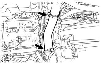
REMOVE NO. 1 RADIATOR HOSE
-
REMOVE NO. 3 ENGINE WIRE (for Cold Area Specification Vehicles)
-
Remove the 2 nuts from the battery terminal.
-
Detach the 3 wire harness clamps.
-
Remove the No. 3 engine wire from the fan shroud.
-
-
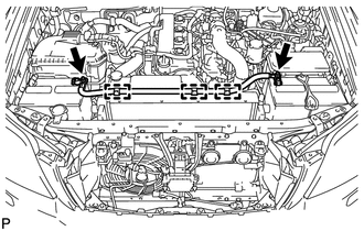
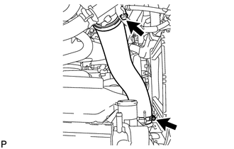
REMOVE NO. 1 AIR HOSE
-
Loosen the 2 clamps.
-
Remove the No. 1 air hose from the inlet pipe and intercooler.
-
-
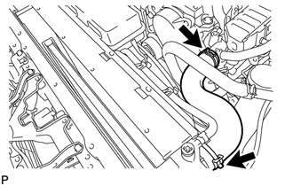
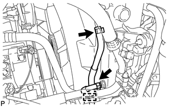
REMOVE INTERCOOLER AIR HOSE
-
Disconnect the No. 2 vacuum transmitting hose from the intercooler.
-
Loosen the 2 clamps.
-
Remove the intercooler hose from the intake pipe and intercooler.
-
-
REMOVE FAN SHROUD
-
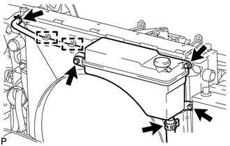
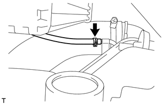
Disconnect the No. 1 water by-pass hose and detach the 2 clamps from the fan shroud.
-
Disconnect the No. 2 water by-pass hose from the radiator reservoir.
-
Remove the 3 bolts and radiator reservoir.
-
for Automatic Transmission:
-
Remove the inlet and outlet oil cooler hoses and detach the clamp from the fan shroud.
-
Disconnect the 2 oil cooler hoses from the radiator.
-
-
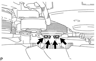
Loosen the 4 nuts holding the fluid coupling and fan.
-
Remove the fan and generator V belt Click here.
-
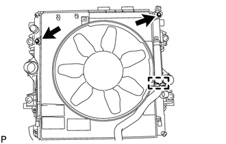
Remove the 2 bolts holding the fan shroud.
-
Remove the 4 nuts for the fan with fluid coupling fan, and then remove the shroud together with the coupling fan.
Note
Be careful not to damage the radiator core.
-
Detach the No. 2 water by-pass hose from the hose clamp on the fan shroud.
-
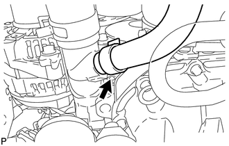
Remove the No. 2 water by-pass hose from the water inlet.
-
Remove the fan pulley from the water pump.
-
-
REMOVE NO. 1 AIR CLEANER HOSE
-
REMOVE AIR CLEANER CAP SUB-ASSEMBLY
-
REMOVE AIR CLEANER FILTER ELEMENT SUB-ASSEMBLY
-
REMOVE AIR CLEANER CASE SUB-ASSEMBLY
-
REMOVE COMPRESSOR OUTLET ELBOW
-
REMOVE VISCOUS WITH MAGNET CLUTCH HEATER ASSEMBLY (for Cold Area Specification Vehicles)
-
REMOVE NO. 1 VISCOUS HEATER BRACKET SUB-ASSEMBLY (for Cold Area Specification Vehicles)
-
DISCONNECT COOLER COMPRESSOR ASSEMBLY (w/ Air Conditioning System)
-
REMOVE GENERATOR BRACKET
-
REMOVE GENERATOR ASSEMBLY
-
REMOVE NO. 1 COMPRESSOR MOUNTING BRACKET
-
REMOVE VENTILATION PIPE
-
REMOVE CYLINDER HEAD COVER SUB-ASSEMBLY
-
REMOVE NO. 1 TIMING BELT COVER
-
REMOVE TIMING BELT
-
REMOVE CAMSHAFT TIMING PULLEY
-
REMOVE NO. 1 TIMING BELT IDLER SUB-ASSEMBLY
-
REMOVE NO. 2 TIMING BELT COVER
-
REMOVE CYLINDER BLOCK INSULATOR
-
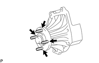
REMOVE ENGINE WATER PUMP ASSEMBLY
-
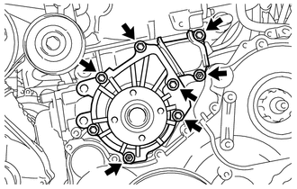
Remove the 2 nuts, 5 bolts, engine water pump assembly and the gasket from the cylinder block sub-assembly.
-
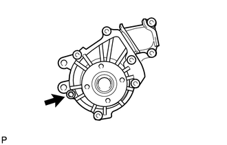
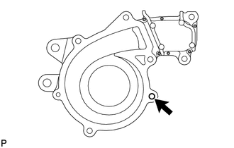
Remove the bolt, water pump assembly without cover and the gasket from the water pump cover.
-
-
REPLACE STUD BOLT
Tech Tips
Perform this procedure only when replacement of the stud bolts is necessary.
-
Remove the 4 stud bolts from the water pump assembly without cover.
-
Install the 4 stud bolts to the water pump assembly without cover.
- Torque:
- 7.8 N*m { 80 kgf*cm, 69 in.*lbf }
-
-
REPLACE WATER PUMP SET RING PIN
Tech Tips
Perform this procedure only when replacement of the water pump set ring pin is necessary.
-
Remove the water pump set ring pin from the water pump cover.
-
Using a plastic-faced hammer, tap in the water pump set ring pin to the water pump cover.
-