INTAKE MANIFOLD REMOVAL
PROCEDURE
-
DISCONNECT CABLE FROM NEGATIVE BATTERY TERMINAL
Note
-
After turning the ignition switch off, waiting time may be required before disconnecting the cable from the battery terminal. Therefore, make sure to read the disconnecting the cable from the battery terminal notice before proceeding with work Click here.
-
When disconnecting the cable, some systems need to be initialized after the cable is reconnected Click here.
-
-
REMOVE ELECTRIC EGR CONTROL VALVE ASSEMBLY (w/ EGR System)
-
Remove the electric EGR control valve assembly Click here.
-
-
DISCONNECT INLET HEATER WATER HOSE (w/o EGR System)
-
DISCONNECT NO. 4 VACUUM TRANSMITTING PIPE SUB-ASSEMBLY (w/o EGR System)
-
REMOVE NO. 1 INTAKE PIPE (w/o EGR System)
-
REMOVE THROTTLE BODY BRACKET (w/o EGR System)
-
REMOVE NO. 1, NO. 2 AND NO. 3 INJECTION PIPE SUB-ASSEMBLY (w/o EGR System)
-
REMOVE AIR CONNECTOR STAY (w/o EGR System)
-
DISCONNECT ENGINE WIRE (w/o EGR System)
-
REMOVE INTAKE AIR CONNECTOR WITH DIESEL THROTTLE BODY ASSEMBLY (w/o EGR System)
-
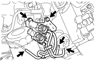
REMOVE MANIFOLD STAY WITH VACUUM SWITCHING VALVE
-
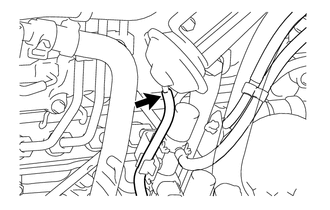
Disconnect the vacuum switching valve connector.
-
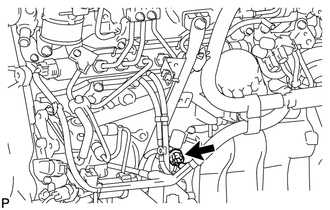
w/o EGR System:
Disconnect the connector.
-
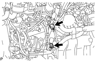
w/ EGR System without EGR Cooler:
Disconnect the 2 connectors.
-
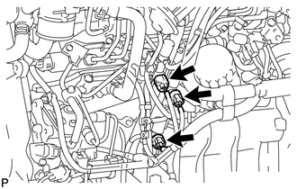
w/ EGR System with EGR Cooler:
Disconnect the 3 connectors.
-
-
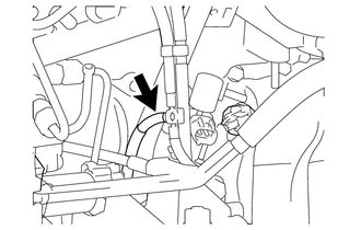
Disconnect the No. 1 vacuum transmitting hose.
-
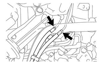
w/ EGR System:
Disconnect the No. 2 vacuum transmitting hose and No. 3 vacuum transmitting hose.
-
w/ EGR Cooler:
Disconnect the No. 3 vacuum transmitting hose.
-
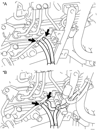
Text in Illustration *A w/o EGR System *B w/ EGR System Disconnect the No. 3 vacuum transmitting hose and No. 4 vacuum transmitting hose.
-
Remove the 2 bolts and manifold stay with vacuum switching valve.
-
-
REMOVE INTAKE PIPE OR HOSE STAY
-
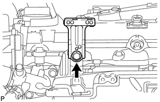
Remove the bolt and intake pipe stay.
-
-
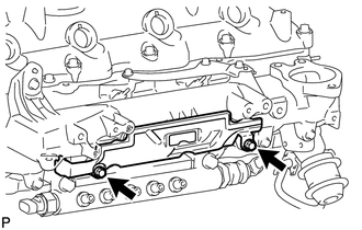
REMOVE VACUUM CONTROL VALVE SET
-
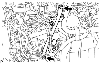
Disconnect the 2 VSV connectors and 3 vacuum hoses.
-
Remove the 2 bolts and vacuum control valve set.
-
-
REMOVE NO. 4 INJECTION PIPE SUB-ASSEMBLY
-
REMOVE NO. 2 NOZZLE LEAKAGE PIPE ASSEMBLY
-
REMOVE INTAKE MANIFOLD INSULATOR
-
Remove the 2 bolts and intake manifold insulator.
-
-
REMOVE INTAKE MANIFOLD
-
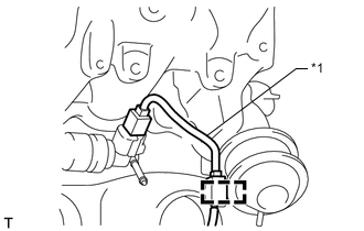
Text in Illustration *1 Sensor Wire Detach the sensor wire connector clamp from the intake manifold.
-
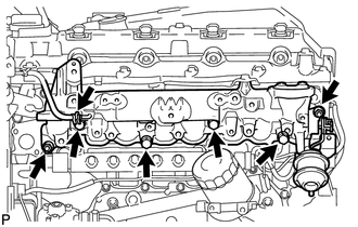
Disconnect the vacuum hose from the intake manifold.
-
Remove the 2 nuts, 4 bolts, intake manifold and gasket.
-