OIL PUMP REMOVAL
PROCEDURE
-
REMOVE ENGINE ASSEMBLY
-
REMOVE IGNITION COIL ASSEMBLY
-
REMOVE GENERATOR ASSEMBLY
-
REMOVE V-RIBBED BELT TENSIONER ASSEMBLY
-
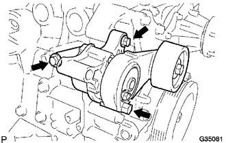
Remove the 2 bolts and V-ribbed belt tensioner assembly.
-
-
REMOVE NO. 1 COMPRESSOR MOUNTING BRACKET
-
REMOVE WATER INLET
-
REMOVE THERMOSTAT
-
REMOVE INTAKE MANIFOLD
-
REMOVE NO. 1 IDLER PULLEY SUB-ASSEMBLY
-
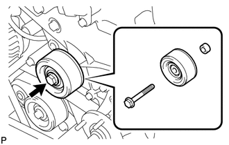
Remove the bolt, No. 1 idler pulley sub-assembly and spacer.
-
-
REMOVE CAMSHAFT POSITION SENSOR (for Intake Side)
-
REMOVE CAMSHAFT POSITION SENSOR (for Exhaust Side)
-
REMOVE CAMSHAFT TIMING OIL CONTROL VALVE ASSEMBLY (for Exhaust Side)
-
REMOVE CRANKSHAFT POSITION SENSOR
-
REMOVE NO. 1 WATER BY-PASS PIPE
-
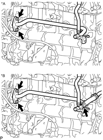
Text in Illustration *A w/o Engine Oil Cooler *B w/ Engine Oil Cooler w/ Engine Oil Cooler:
Slide the clip and disconnect the No. 6 water by-pass hose from the No. 1 water by-pass pipe.
-
Remove the 2 nuts, bolt, No. 1 water by-pass pipe and gasket.
-
-
REMOVE CYLINDER HEAD COVER SUB-ASSEMBLY
-
Slide the clip and disconnect the PCV hose from the PCV valve sub-assembly.
-
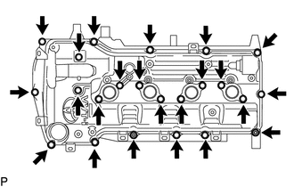
Remove the 21 bolts, 2 nuts, 2 plate washers, 2 seal washers and cylinder head cover sub-assembly.
-
Remove the gasket from the cylinder head cover sub-assembly.
-
Remove the No. 1 camshaft bearing cap oil hole gasket from the cylinder head cover spacer.
-
-
REMOVE CRANKSHAFT PULLEY
-
REMOVE OIL PAN COVER SILENCER
-
Remove the 2 No. 1 oil pan plugs and oil pan cover silencer.
-
-
REMOVE NO. 2 OIL PAN SUB-ASSEMBLY
-
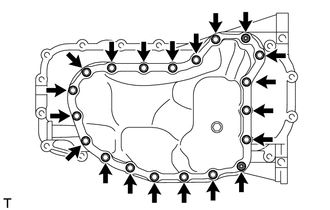
Remove the oil pan drain plug and gasket.
-
Remove the 16 bolts, 2 adjusting screws, and 2 nuts.
-
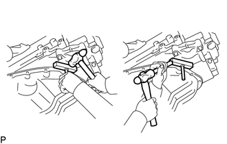
Insert the blade of an oil pan seal cutter between the oil pans. Cut through the applied sealer and remove the No. 2 oil pan sub-assembly.
Note
Be careful not to damage the contact surfaces of the oil pans.
-
-
REMOVE OIL PAN SUB-ASSEMBLY
-
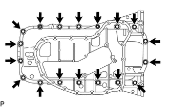
Remove the 16 bolts and 2 nuts.
-
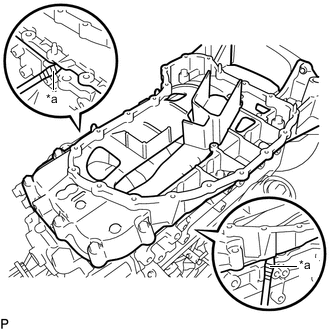
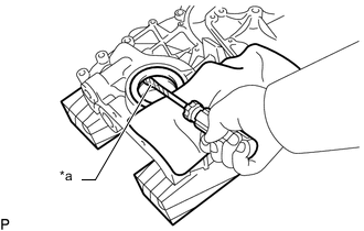
Text in Illustration *a Protective Tape Remove the oil pan sub-assembly by prying between the oil pan sub-assembly and cylinder block with a screwdriver.
Note
Be careful not to damage the contact surfaces of the cylinder block and oil pan sub-assembly.
Tech Tips
Tape the screwdriver tip before use.
-
Remove the gasket from the oil strainer sub-assembly.
-
-
REMOVE TIMING CHAIN COVER SUB-ASSEMBLY
-
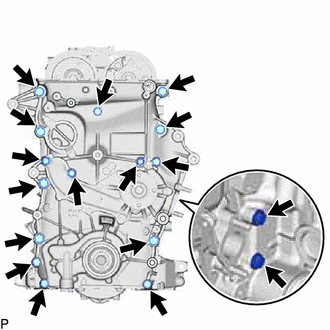
Remove the 16 bolts and nut shown in the illustration.
-
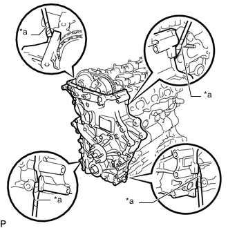
Text in Illustration *a Protective Tape Using a screwdriver wrapped in protective tape, remove the timing chain cover sub-assembly by prying the points in the illustration.
Note
Do not damage the surrounding parts.
Tech Tips
Tape the screwdriver tip before use.
-
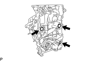
Remove the 3 O-rings from the timing chain cover sub-assembly.
-
-
REMOVE ENGINE WATER PUMP ASSEMBLY
-
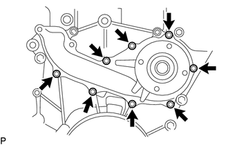
Remove the 8 bolts, engine water pump assembly and gasket.
-
-
REMOVE TIMING CHAIN COVER OIL SEAL
-
Text in Illustration *a Protective Tape Using a screwdriver wrapped in protective tape, pry out the timing chain cover oil seal from the timing chain cover sub-assembly.
Note
Be careful not to damage the timing chain cover sub-assembly.
Tech Tips
Tape the screwdriver tip before use.
-