LIGHTING SYSTEM High Beam Headlight Circuit
DESCRIPTION
-
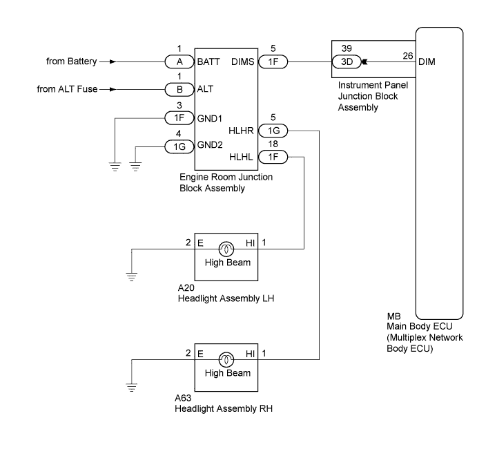
The main body ECU (multiplex network body ECU) controls the high beam headlights via the engine room junction block assembly.
for Halogen Headlight:
-
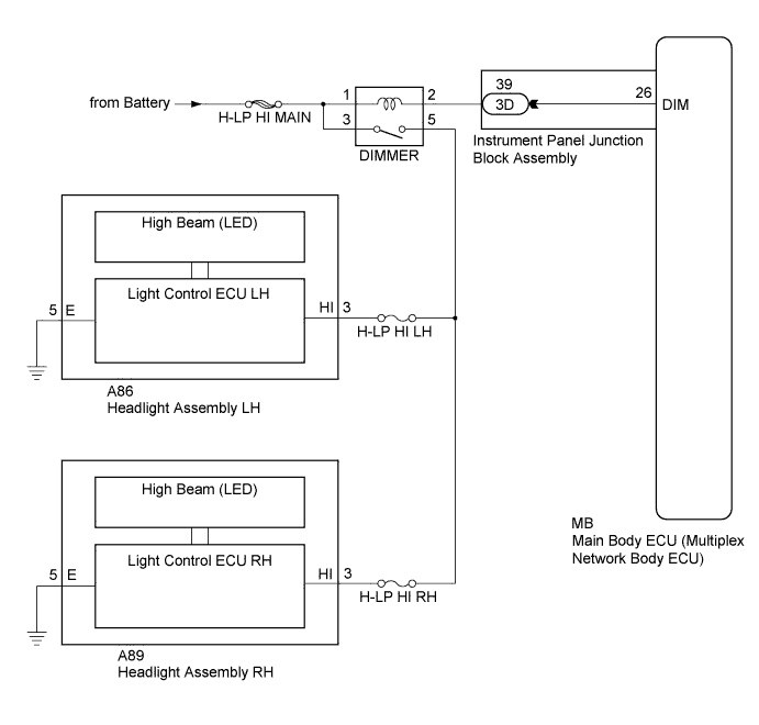
The main body ECU (multiplex network body ECU) controls the high beam headlights via the DIMMER relay.
for LED Headlight:
WIRING DIAGRAM
-
for LED Headlight:
-
for Halogen Headlight:
INSPECTION PROCEDURE
Note
Inspect the fuses and lights for circuits related to this system before performing the following inspection procedure.
PROCEDURE
-
PERFORM ACTIVE TEST USING TECHSTREAM
-
Connect the Techstream to the DLC3.
-
Turn the ignition switch to ON.
-
Turn the Techstream on.
-
Enter the following menus: Body Electrical / Main Body / Active Test.
-
Perform the Active Test according to the display on the Techstream.
Main Body Tester Display Test Part Control Range Diagnostic Note Head Light Hi High beam headlights ON/OFF - OK High beam headlights illuminate. Result Result Proceed to OK A NG (for Halogen Headlight) B NG (for LED Headlight) C
B 
INSPECT ENGINE ROOM JUNCTION BLOCK ASSEMBLY Click here
C
INSPECT DIMMER RELAY Click here
A 
PROCEED TO NEXT SUSPECTED AREA SHOWN IN PROBLEM SYMPTOMS TABLE Click here
-
-
INSPECT ENGINE ROOM JUNCTION BLOCK ASSEMBLY
-
Using a voltmeter, check the signal reading of the engine room junction block assembly Click here.
OK Output signal reading is normal.
NG 
INSPECT ENGINE ROOM JUNCTION BLOCK ASSEMBLY (RESULTS OF SIGNAL READING CHECK) Click here
OK 
-
-
CHECK HARNESS AND CONNECTOR (ENGINE ROOM JUNCTION BLOCK ASSEMBLY POWER SOURCE AND BODY GROUND)
-
Remove the engine room junction block assembly from the engine room relay block and junction block assembly Click here.
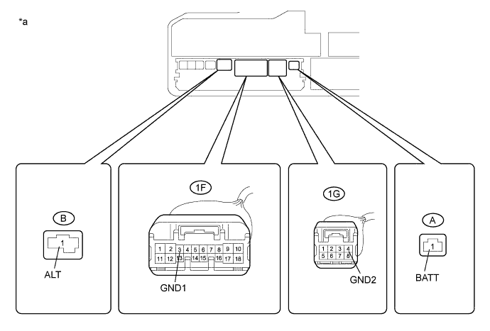
Text in Illustration *a Component without engine room junction block assembly
(Engine Room Relay Block and Junction Block Assembly)
- - -
Measure the voltage according to the value(s) in the table below.
Standard Voltage Tester Connection Condition Specified Condition A-1 (BATT) - Body ground Always 11 to 14 V B-1 (ALT) - Body ground Always 11 to 14 V -
Measure the resistance according to the value(s) in the table below.
Standard Resistance Tester Connection Condition Specified Condition 1F-3 (GND1) - Body ground Always Below 1 Ω 1G-4 (GND2) - Body ground Always Below 1 Ω
NG
REPAIR OR REPLACE HARNESS OR CONNECTOR
OK
-
-
CHECK HARNESS AND CONNECTOR (ENGINE ROOM JUNCTION BLOCK ASSEMBLY - INSTRUMENT PANEL JUNCTION BLOCK ASSEMBLY
-
Disconnect the 3D instrument panel junction block assembly connector.
-
Measure the resistance according to the value(s) in the table below.
Standard Resistance Tester Connection Condition Specified Condition 1F-5 (DIMS) - 3D-39 Always Below 1 Ω 3D-39 - Body ground Always 10 kΩ or higher
NG
REPAIR OR REPLACE HARNESS OR CONNECTOR
OK
-
-
INSPECT INSTRUMENT PANEL JUNCTION BLOCK ASSEMBLY
-
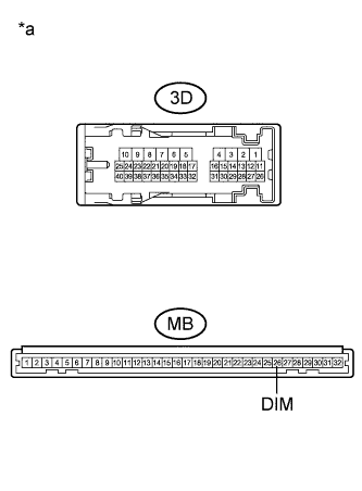
Text in Illustration *a Component without harness connected
(Instrument Panel Junction Block Assembly)
Remove the instrument panel junction block assembly Click here.
-
Remove the main body ECU (multiplex network body ECU) from the instrument panel junction block assembly.
-
Measure the resistance according to the value(s) in the table below.
Standard Resistance Tester Connection Condition Specified Condition 3D-39 - MB-26 (DIM) Always Below 1 Ω
NG
REPLACE INSTRUMENT PANEL JUNCTION BLOCK ASSEMBLY Click here
OK
-
-
REPLACE ENGINE ROOM JUNCTION BLOCK ASSEMBLY
-
Replace the engine room junction block assembly with a new or known good one Click here.
-
Check that the high beam headlights operate normally.
OK High beam headlights operate normally.
NG
REPLACE MAIN BODY ECU (MULTIPLEX NETWORK BODY ECU) Click here
OK
END (ENGINE ROOM JUNCTION BLOCK ASSEMBLY WAS DEFECTIVE)
-
-
INSPECT DIMMER RELAY
-
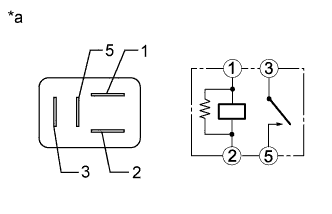
Text in Illustration *a Component without harness connected
(DIMMER Relay)
Remove the DIMMER relay from the No. 2 engine room relay block and junction block assembly.
-
Measure the resistance according to the value(s) in the table below.
Standard Resistance Tester Connection Condition Specified Condition 3 - 5 Voltage not applied between terminals 1 and 2 10 kΩ or higher 3 - 5 Voltage applied between terminals 1 and 2 Below 1 Ω
NG
REPLACE DIMMER RELAY
OK
-
-
CHECK HARNESS AND CONNECTOR (H-LP HI MAIN FUSE - DIMMER RELAY)
-
Measure the voltage according to the value(s) in the table below.
Standard Voltage Tester Connection Condition Specified Condition Relay Terminal 1 - Body ground Always 11 to 14 V Relay Terminal 3 - Body ground Always 11 to 14 V
NG
REPAIR OR REPLACE HARNESS OR CONNECTOR
OK
-
-
CHECK HARNESS AND CONNECTOR (DIMMER RELAY - HEADLIGHT ASSEMBLY)
-
Disconnect the A86 headlight assembly LH connector.
-
Disconnect the A89 headlight assembly RH connector.
-
Measure the resistance according to the value(s) in the table below.
Standard Resistance Tester Connection Condition Specified Condition Relay Terminal 5 - A86-3 (HI) Always Below 1 Ω Relay Terminal 5 - A89-3 (HI) Always Below 1 Ω Relay Terminal 5 - Body ground Always 10 kΩ or higher
NG
REPAIR OR REPLACE HARNESS OR CONNECTOR
OK
-
-
CHECK HARNESS AND CONNECTOR (DIMMER RELAY - INSTRUMENT PANEL JUNCTION BLOCK ASSEMBLY)
-
Disconnect the 3D instrument panel junction block assembly connector.
-
Measure the resistance according to the value(s) in the table below.
Standard Resistance Tester Connection Condition Specified Condition Relay Terminal 2 - 3D-39 Always Below 1 Ω Relay Terminal 2 - Body ground Always 10 kΩ or higher
NG
REPAIR OR REPLACE HARNESS OR CONNECTOR
OK
-
-
INSPECT INSTRUMENT PANEL JUNCTION BLOCK ASSEMBLY
-
Text in Illustration *a Component without harness connected
(Instrument Panel Junction Block Assembly)
Remove the instrument panel junction block assembly Click here.
-
Remove the main body ECU (multiplex network body ECU) from the instrument panel junction block assembly.
-
Measure the resistance according to the value(s) in the table below.
Standard Resistance Tester Connection Condition Specified Condition 3D-39 - MB-26 (DIM) Always Below 1 Ω
NG
REPLACE INSTRUMENT PANEL JUNCTION BLOCK ASSEMBLY Click here
OK
REPLACE MAIN BODY ECU (MULTIPLEX NETWORK BODY ECU) Click here
-