LIGHTING SYSTEM, Diagnostic DTC:B1244

| DTC Code | DTC Name |
|---|---|
| B1244 | Light Sensor Circuit Malfunction |
DESCRIPTION
This DTC is stored when a failure of the automatic light control sensor circuit is detected.
| DTC Code | DTC Detection Condition | Trouble Area |
|---|---|---|
| B1244 | When either condition below is met:
|
|
WIRING DIAGRAM
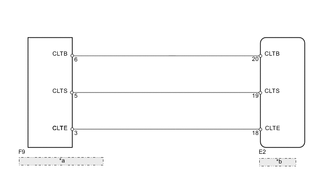
| *a | Automatic Light Control Sensor |
| *b | Main Body ECU |
PROCEDURE
-
CHECK FOR DTC
-
Clear the DTC Click here.
-
Recheck for DTC Click here.
OK DTC B1244 is not output.
OK 
USE SIMULATION METHOD TO CHECK Click here
NG 
-
-
READ VALUE USING INTELLIGENT TESTER (AUTOMATIC LIGHT CONTROL SENSOR)
-
Operate the intelligent tester according to the display and select "Data List".
Main Body Tester Display Measurement Item/Range Normal Condition Diagnostic Note Illumination Rate Info Illumination rate/min.: 0, max.: 99.99 Actual illumination rate is displayed - OK Output illuminance is as shown in table above.
OK
REPLACE MAIN BODY ECU
NG
-
-
CHECK MAIN BODY ECU (LIGHT CONTROL SENSOR VOLTAGE)
-
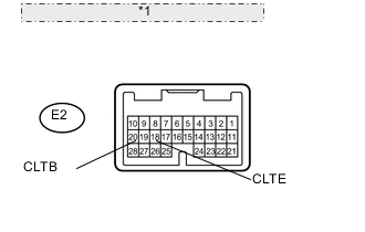
*1 Component with harness connected: (Main Body ECU) Measure the voltage according to the value(s) in the table below.
Standard Voltage Tester Connection Switch Condition Specified Condition E2-20 (CLTB) - E2-18 (CLTE) Ignition switch ON 11 to 14 V Ignition switch off Below 1 V
NG
REPLACE MAIN BODY ECU
OK
-
-
CHECK HARNESS AND CONNECTOR (MAIN BODY ECU - AUTOMATIC LIGHT CONTROL SENSOR)
-
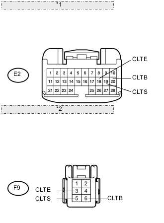
*1 Front view of wire harness connector: (to Main Body ECU) *2 Front view of wire harness connector: (to Automatic Light Control Sensor) Disconnect the E2 ECU connector.
-
Disconnect the F9 sensor connector.
-
Measure the resistance according to the value(s) in the table below.
Standard Resistance Tester Connection Condition Specified Condition E2-20 (CLTB) - F9-6 (CLTB) Always Below 1 Ω E2-19 (CLTS) - F9-5 (CLTS) E2-18 (CLTE) - F9-3 (CLTE) E2-20 (CLTB) - Body ground Always 10 kΩ or higher E2-19 (CLTS) - Body ground E2-18 (CLTE) - Body ground
OK
REPLACE AUTOMATIC LIGHT CONTROL SENSOR Click here
NG
REPAIR OR REPLACE HARNESS OR CONNECTOR
-