WINDOW DEFOGGER SYSTEM Rear Window Defogger System does not Operate
DESCRIPTION
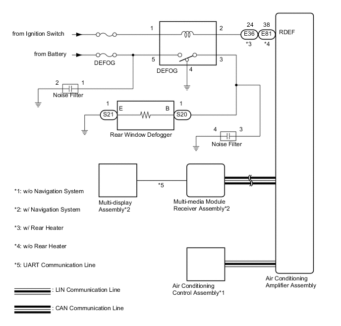
When the rear window defogger switch is turned on, a rear window defogger activation request signal is sent via the LIN communication line*1 or CAN communication line and UART communication line*2 to the air conditioning amplifier assembly. Then the air conditioning amplifier assembly operates the rear window defogger. When the on signal from the switch is received, the defogger relay (DEFOG) is operated for 15 minutes. Also, if the off signal from the switch is received within 15 minutes, the defogger relay (DEFOG) operation is stopped.
Tech Tips
*1: w/o Navigation System
*2: w/ Navigation System
WIRING DIAGRAM
CAUTION / NOTICE / HINT
Note
Inspect the fuses for circuits related to this system before performing the following inspection procedure.
PROCEDURE
-
CHECK FOR DTC
-
*1: w/o Navigation System
-
*2: w/ Navigation System
-
Check if the LIN communication system*1 or CAN communication system*2 is functioning normally.
-
LIN communication system: Click here
-
CAN communication system (for LHD): Click here
-
CAN communication system (for RHD): Click here
Result Result Proceed to DTC is not output A LIN DTC is output*1 B CAN DTC is output (for LHD)*2 C CAN DTC is output (for RHD)*2 D -
B 
GO TO LIN COMMUNICATION SYSTEM Click here
C
GO TO CAN COMMUNICATION SYSTEM Click here
D
GO TO CAN COMMUNICATION SYSTEM Click here
A 
-
-
PERFORM ACTIVE TEST USING INTELLIGENT TESTER (DEFOGGER RELAY)
-
Select the Active Test using the intelligent tester to generate a control command, and then check that the rear window defogger operates Click here.
Air Conditioner Tester Display Test Part Control Range Diagnostic Note Defogger Relay (Rear) Rear window defogger relay operation OFF or ON - OK On intelligent tester screen, item changes between ON and OFF according to above chart. Result Result Proceed to OK (w/o Navigation System) A OK (w/ Navigation System) B NG C
B 
CHECK NAVIGATION SYSTEM Click here
C
INSPECT DEFOGGER RELAY (DEFOG) Click here
A
-
-
REPLACE AIR CONDITIONING CONTROL ASSEMBLY
-
Temporarily replace the air conditioning control assembly with a new or normally functioning one Click here.
NEXT
-
-
CHECK WINDOW DEFOGGER SYSTEM
-
Turn the ignition switch ON.
-
Check that pressing the defogger switch illuminates the indicator and warms the rear window surface.
-
Check that after approximately 15 minutes, the indicator light turns off and the rear window defogger deactivates.
OK Rear window defogger system functioning normally.
OK
END (AIR CONDITIONING CONTROL ASSEMBLY IS DEFECTIVE)
NG
REPLACE AIR CONDITIONING AMPLIFIER ASSEMBLY Click here
-
-
CHECK NAVIGATION SYSTEM
-
Check if the navigation system function properly Click here.
OK Navigation system function properly.
NG
GO TO NAVIGATION SYSTEM Click here
OK
-
-
REPLACE AIR CONDITIONING AMPLIFIER ASSEMBLY
-
Temporarily replace the air conditioning amplifier assembly with a new or normally functioning one Click here.
NEXT
-
-
CHECK WINDOW DEFOGGER SYSTEM
-
Turn the ignition switch ON.
-
Check that pressing the defogger switch illuminates the indicator and warms the rear window surface.
-
Check that after approximately 15 minutes, the indicator light turns off and the rear window defogger deactivates.
OK Rear window defogger system functioning normally.
OK
END (AIR CONDITIONING AMPLIFIER ASSEMBLY IS DEFECTIVE)
NG
-
-
REPLACE MULTI-MEDIA MODULE RECEIVER ASSEMBLY
-
Temporarily replace the multi-media module receiver assembly with a new or normally functioning one Click here.
NEXT
-
-
CHECK WINDOW DEFOGGER SYSTEM
-
Turn the ignition switch ON.
-
Check that pressing the defogger switch illuminates the indicator and warms the rear window surface.
-
Check that after approximately 15 minutes, the indicator light turns off and the rear window defogger deactivates.
OK Rear window defogger system functioning normally.
OK
END (MULTI-MEDIA MODULE RECEIVER ASSEMBLY IS DEFECTIVE)
NG
REPLACE MULTI-DISPLAY Click here
-
-
INSPECT DEFOGGER RELAY (DEFOG)
-
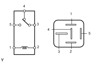
Remove the defogger relay from the engine room junction block.
-
Measure the resistance according to the value(s) in the table below.
Standard Resistance Tester Connection Condition Specified Condition 3 - 4 Battery voltage is not applied to terminals 1 and 2 Below 1 Ω 3 - 5 10 kΩ or higher 3 - 4 Battery voltage is applied to terminals 1 and 2 10 kΩ or higher 3 - 5 Below 1 Ω Result Result Proceed to OK (w/ Rear Heater) A OK (w/o Rear Heater) B NG C
B
CHECK HARNESS AND CONNECTOR (DEFOGGER RELAY - AIR CONDITIONING AMPLIFIER AND BATTERY) Click here
C
REPLACE DEFOGGER RELAY
A
-
-
CHECK HARNESS AND CONNECTOR (DEFOGGER RELAY - AIR CONDITIONING AMPLIFIER AND BATTERY)
-
Remove the defogger relay from the engine room relay block.
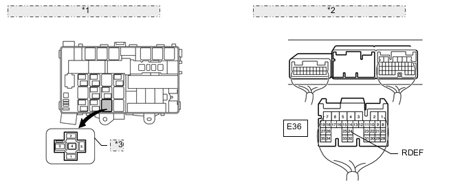
*1 Component without relay connected: (Engine Room Relay Block, Junction Block) *2 Rear view of wire harness connector: (to Air Conditioning Amplifier) *3 Defogger Relay (DEFOG) -
Disconnect the E36 air conditioning amplifier assembly connector.
-
Measure the voltage according to the value(s) in the table below.
Standard Voltage Tester Connection Condition Specified Condition Defogger relay terminal 1 - Body ground Ignition switch ON 11 to 14 V Defogger relay terminal 5 - Body ground Always 11 to 14 V -
Measure the resistance according to the value(s) in the table below.
Standard Resistance Tester Connection Condition Specified Condition Defogger relay terminal 2 - E36-24 (RDEF) Always Below 1 Ω
NG
REPAIR OR REPLACE HARNESS OR CONNECTOR
OK
-
-
CHECK HARNESS AND CONNECTOR (REAR WINDOW DEFOGGER - DEFOGGER RELAY AND BODY GROUND)
-
Disconnect the S20 and S21 defogger wire connectors.
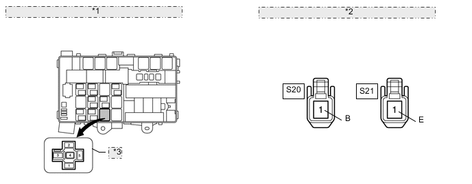
*1 Component without relay connected: (Engine Room Relay Block, Junction Block) *2 Component without wire harness connected: (Rear Window Defogger Wire) *3 Defogger Relay (DEFOG) -
Remove the defogger relay from the engine room relay block.
-
Measure the resistance according to the value(s) in the table below.
Standard Resistance Tester Connection Condition Specified Condition S20-1(B) - Defogger relay terminal 3 Always Below 1 Ω S21-1(B) - Body ground Defogger relay terminal 4 - Body ground S20-1(B) - Body ground Always 10 kΩ or higher
NG
REPAIR OR REPLACE HARNESS OR CONNECTOR
OK
-
-
CHECK REAR WINDOW DEFOGGER WIRE
-
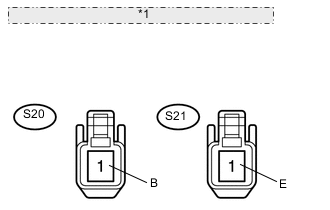
*1 Component without wire harness connected: (Rear Window Defogger Wire) Disconnect the S20 and S21 defogger wire connectors.
-
Measure the resistance according to the value(s) in the table below.
Standard Resistance Tester Connection Switch Condition Specified Condition S20-1 (B) - S21-1 (E) Ignition switch ON and defogger switch on 10 kΩ or higher
OK
REPLACE BACK WINDOW GLASS Click here
NG
REPLACE AIR CONDITIONING AMPLIFIER ASSEMBLY Click here
-
-
CHECK HARNESS AND CONNECTOR (DEFOGGER RELAY - AIR CONDITIONING AMPLIFIER AND BATTERY)
-
Remove the defogger relay from the engine room relay block.
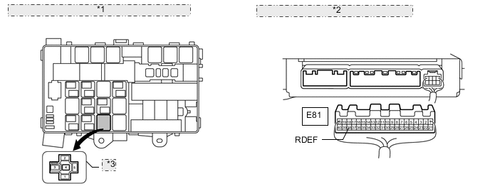
*1 Component without relay connected: (Engine Room Relay Block, Junction Block) *2 Rear view of wire harness connector: (to Air Conditioning Amplifier) *3 Defogger Relay (DEFOG) -
Disconnect the E81 air conditioning amplifier assembly connector.
-
Measure the voltage according to the value(s) in the table below.
Standard Voltage Tester Connection Condition Specified Condition Defogger relay terminal 1 - Body ground Ignition switch ON 11 to 14 V Defogger relay terminal 5 - Body ground Always 11 to 14 V -
Measure the resistance according to the value(s) in the table below.
Standard Resistance Tester Connection Condition Specified Condition Defogger relay terminal 2 - E81-38 (RDEF) Always Below 1 Ω
NG
REPAIR OR REPLACE HARNESS OR CONNECTOR
OK
-
-
CHECK HARNESS AND CONNECTOR (REAR WINDOW DEFOGGER - DEFOGGER RELAY AND BODY GROUND)
-
Disconnect the S20 and S21 defogger wire connectors.
*1 Component without relay connected: (Engine Room Relay Block, Junction Block) *2 Component without wire harness connected: (Rear Window Defogger Wire) *3 Defogger Relay (DEFOG) -
Remove the defogger relay from the engine room relay block.
-
Measure the resistance according to the value(s) in the table below.
Standard Resistance Tester Connection Condition Specified Condition S20-1(B) - Defogger relay terminal 3 Always Below 1 Ω S21-1(B) - Body ground Defogger relay terminal 4 - Body ground S20-1(B) - Body ground Always 10 kΩ or higher
NG
REPAIR OR REPLACE HARNESS OR CONNECTOR
OK
-
-
CHECK REAR WINDOW DEFOGGER WIRE
-
*1 Component without wire harness connected: (Rear Window Defogger Wire) Disconnect the S20 and S21 defogger wire connectors.
-
Measure the voltage according to the value(s) in the table below.
Standard Voltage Tester Connection Switch Condition Specified Condition S20-1 (B) - S21-1 (E) Ignition switch ON and defogger switch on 11 to 14 V
OK
REPLACE BACK WINDOW GLASS Click here
NG
REPLACE AIR CONDITIONING AMPLIFIER ASSEMBLY Click here
-