HEATER WATER PUMP(w/ Viscous Heater) INSTALLATION
PROCEDURE
-
INSTALL IDLER PULLEY BRACKET (w/ Belt Tension Side)
-
Install the bracket with the 3 bolts.
- Torque:
- 48.5 N*m { 495 kgf*cm, 36 ft.*lbf }
-
-
INSTALL IDLER PULLEY BRACKET
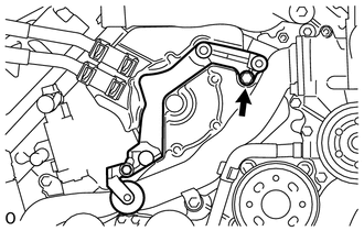
-
Install the bracket with the bolt.
- Torque:
- 48.5 N*m { 495 kgf*cm, 36 ft.*lbf }
-
-
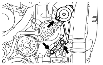
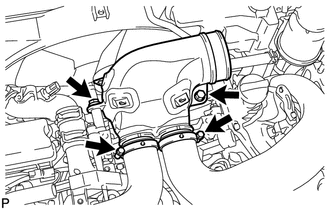
INSTALL VISCOUS WITH MAGNET CLUTCH HEATER ASSEMBLY
-
Install the heater assembly with the 2 bolts.
- Torque:
- 48.5 N*m { 495 kgf*cm, 36 ft.*lbf }
-
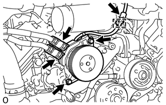
Connect the 2 heater hoses.
-
Using pliers, grip the claws of the clips and slide the 2 clips.
-
Connect the connector and attach the clamp.
-
-
INSTALL IDLER PULLEY ASSEMBLY
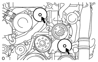
-
Install the 2 idler pulleys with the 2 bolts.
- Torque:
- 48.5 N*m { 495 kgf*cm, 36 ft.*lbf }
-
-
INSTALL RADIATOR ASSEMBLY
-
Install the radiator assembly Click here.
-
-
INSTALL RADIATOR RESERVE TANK ASSEMBLY
-
INSTALL FAN SHROUD WITH FAN
-
INSTALL OIL COOLER HOSE (w/ Air Cooled Transmission Oil Cooler)
-
INSTALL NO. 2 RADIATOR HOSE
-
INSTALL NO. 1 RADIATOR HOSE
-
INSTALL VANE PUMP ASSEMBLY
-
INSTALL VANE PUMP OIL RESERVOIR ASSEMBLY
-
INSTALL V-RIBBED BELT
-
INSTALL INTAKE AIR CONNECTOR
-
Connect the intake air connector to the No. 1 and No. 2 air cleaner pipes.
-
Install the connector with the 2 bolts.
- Torque:
- 21 N*m { 214 kgf*cm, 15 ft.*lbf }
-
Tighten the 2 hose clamps.
- Torque:
- 6.3 N*m { 64 kgf*cm, 56 in.*lbf }
-
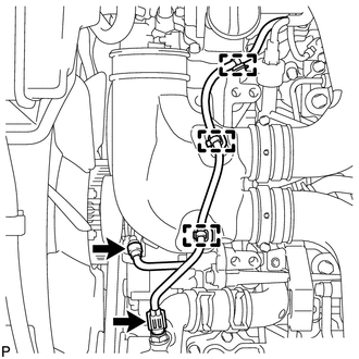
Attach the 3 wire harness clamps.
-
Connect the 2 connectors to the water temperature sensor and viscous heater.
-
-
TEMPORARILY INSTALL NO. 1 AIR CLEANER HOSE
-
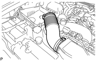
Temporarily install the air cleaner hose to the intake air connector.
-
-
INSTALL AIR CLEANER CAP SUB-ASSEMBLY
-
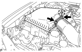
Align the protrusion of the air cleaner cap and concave portion of the air cleaner hose.
-
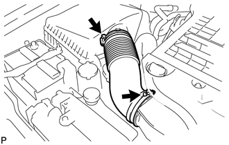
Connect the air cleaner cap to the air cleaner hose, and install the air cleaner cap with the 3 clamps.
-
Tighten the 2 hose clamps and connect the connector.
- Torque:
- 2.5 N*m { 25 kgf*cm, 22 in.*lbf }
-
-
INSTALL NO. 1 ENGINE COVER SUB-ASSEMBLY
-
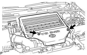
Install the engine cover with the 2 nuts.
- Torque:
- 8.0 N*m { 82 kgf*cm, 71 in.*lbf }
-
-
INSTALL NO. 3 ENGINE ROOM WIRE
-
INSTALL UPPER RADIATOR SUPPORT SEAL
-
ADD ENGINE COOLANT
-
INSTALL NO. 1 ENGINE UNDER COVER SUB-ASSEMBLY
-
INSTALL FRONT FENDER SPLASH SHIELD SUB-ASSEMBLY LH
-
for Standard:
Install the front fender splash shield Click here.
-
w/ Winch:
Install the front fender splash shield Click here.
-
-
INSTALL FRONT FENDER SPLASH SHIELD SUB-ASSEMBLY RH
-
for Standard:
Install the front fender splash shield Click here.
-
w/ Winch:
Install the front fender splash shield Click here.
-
-
CONNECT CABLE TO NEGATIVE BATTERY TERMINAL
Note
When disconnecting the cable, some systems need to be initialized after the cable is reconnected Click here.
-
CHECK FOR ENGINE COOLANT LEAKS