METER / GAUGE SYSTEM Oil Pressure Gauge Malfunction
DESCRIPTION
The oil pressure sender detects the oil pressure generated when the engine is started. The combination meter determines that the engine is running when the engine speed is 400 rpm or more, and determines that the engine is cranking when the engine speed is 200 rpm or less. The oil pressure receiver gauge detects and indicates the oil pressure applied to the oil pressure sender.
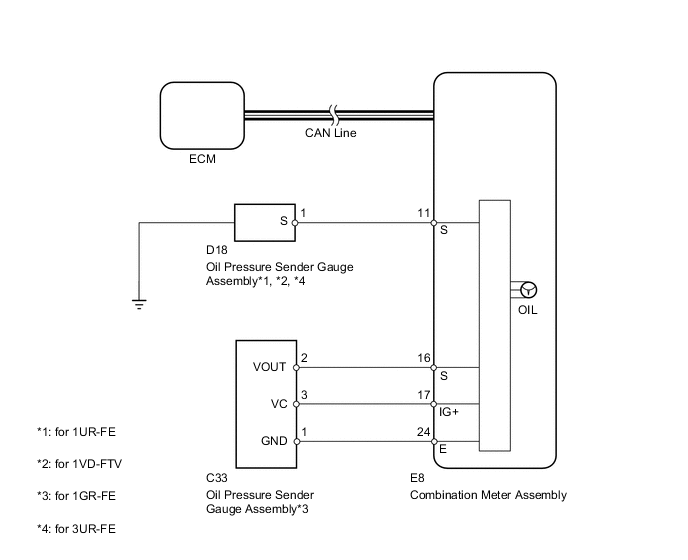
WIRING DIAGRAM
PROCEDURE
-
CHECK CAN COMMUNICATION SYSTEM
-
Check for DTCs Click here.
Result Result Proceed to CAN communication system DTC is not output A CAN communication system (for LHD) DTC is output B CAN communication system (for RHD) DTC is output C
B 
Go to CAN COMMUNICATION SYSTEM Click here
C
Go to CAN COMMUNICATION SYSTEM Click here
A 
-
-
PERFORM ACTIVE TEST USING INTELLIGENT TESTER (OIL PRESSURE SENSOR)
-
Operate the intelligent tester according to the display and select Active Test Click here.
Combination Meter Tester Display Test Part Control Range Diagnostic Note Oil Pressure Meter Operation Oil pressure receiver gauge LOW, 1/4, 1/2, 3/4 or HIGH Perform the test with the vehicle stopped and engine idling. OK Needle indication is normal. Result Result Proceed to OK A NG (w/ Multi-information Display) B NG (w/o Multi-information Display) C
B
REPLACE COMBINATION METER ASSEMBLY Click here
C
REPLACE COMBINATION METER ASSEMBLY Click here
A
-
-
INSPECT OIL PRESSURE GAUGE ASSEMBLY (OIL PRESSURE SENSOR)
-
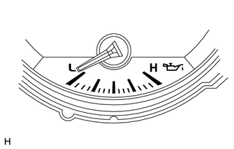
Check that the needle moves in accordance with the engine speed.
OK Needle is as shown in illustration when engine is stopped. Needle moves when engine is running. Result Result Proceed to Oil pressure receiver gauge operates correctly according to engine condition A Oil pressure receiver gauge does not operate correctly according to engine condition (for 1GR-FE) B Oil pressure receiver gauge does not operate correctly according to engine condition (for 1UR-FE) C Oil pressure receiver gauge does not operate correctly according to engine condition (for 3UR-FE) D Oil pressure receiver gauge does not operate correctly according to engine condition (for 1VD-FTV) E
B
REPLACE OIL PRESSURE SENDER GAUGE ASSEMBLY Click here
C
REPLACE OIL PRESSURE SENDER GAUGE ASSEMBLY Click here
D
REPLACE OIL PRESSURE SENDER GAUGE ASSEMBLY Click here
E
REPLACE OIL PRESSURE SENDER GAUGE ASSEMBLY Click here
A
-
-
CHECK HARNESS AND CONNECTOR (COMBINATION METER - OIL PRESSURE SENSOR)
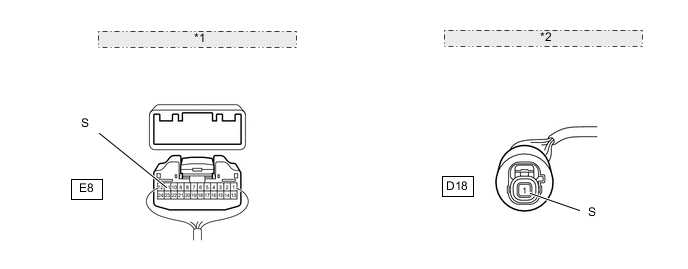
*1 Rear view of harness connector: (to Combination Meter Assembly) *2 Front view of harness connector: (to Oil Pressure Sensor)
-
for 1UR-FE, 3UZ-FE, 1VD-FTV:
-
Disconnect the E8 meter connector.
-
Disconnect the D18 gauge connector.
-
Measure the resistance according to the value(s) in the table below.
Standard Resistance Tester Connection Condition Specified Condition E8-11 (S) - D18-1 (S) Always Below 1 Ω E8-11 (S) or D18-1 (S) - Body ground Always 10 kΩ or higher
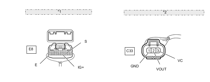
*1 Rear view of wire harness connector: (to Combination Meter Assembly) *2 Front view of wire harness connector: (to Oil Pressure Sender Gauge Assembly) -
-
for 1GR-FE:
-
Disconnect the E8 meter connector.
-
Disconnect the C33 gauge connector.
-
Measure the resistance according to the value(s) in the table below.
Standard Resistance Tester Connection Condition Specified Condition E8-16 (S) - C33-2 (VOUT) Always Below 1 Ω E8-17 (IG+) - C33-3 (VC) E8-24 (E) - C33-1 (GND) E8-16 (S) or C33-2 (VOUT) - Body ground Always 10 kΩ or higher E8-17 (IG+) or C33-3 (VC) - Body ground
Result Result Proceed to NG A OK (w/ Multi-information Display) B OK (w/o Multi-information Display) C -
A
REPAIR OR REPLACE HARNESS OR CONNECTOR
B
REPLACE COMBINATION METER ASSEMBLY Click here
C
REPLACE COMBINATION METER ASSEMBLY Click here
-