REAR SEAT ENTERTAINMENT SYSTEM Display Signal Circuit between Multi-display Controller and Television Display
DESCRIPTION
This is the display signal circuit between the multi-media module receiver assembly and the television display assembly.
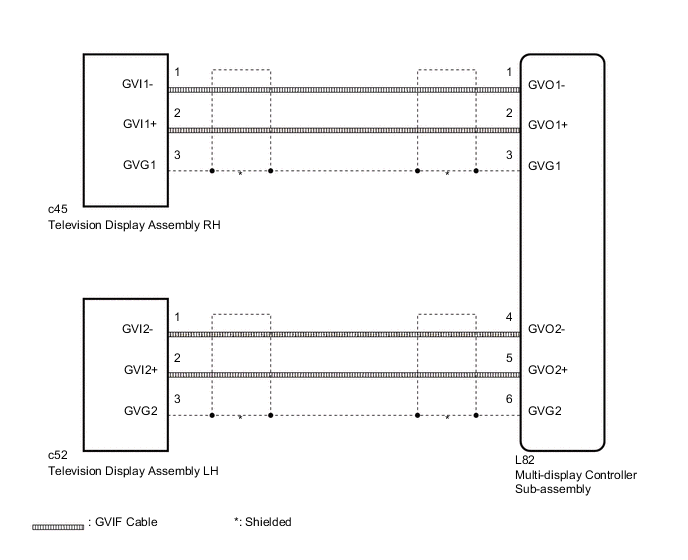
WIRING DIAGRAM
PROCEDURE
-
CHECK HARNESS AND CONNECTOR (GVIF CABLE)
-
Check if the GVIF cable connectors between the multi-display controller sub-assembly and the television display assembly have any connection problems Click here.
OK There are no connection problems.
NG 
REMOVE CONNECTION PROBLEMS (GVIF CABLE)
OK 
-
-
CHECK HARNESS AND CONNECTOR (GVIF CABLE)
-
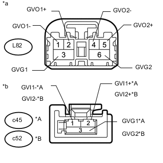
Text in Illustration *A for RH *B for LH *a GVIF Cable
(to Multi-display Controller Sub-assembly)
*b GVIF Cable
(to Television Display Assembly)
Remove the GVIF cable from the multi-display controller sub-assembly and television display assembly.
-
Measure the resistance according to the value(s) in the table below.
Standard Resistance for RH Tester Connection Condition Specified Condition L82-1 (GVO1-) - c45-1 (GVI1-) Always Below 1 Ω L82-2 (GVO1+) - c45-2 (GVI1+) Always Below 1 Ω L82-3 (GVG1) - c45-3 (GVG1) Always Below 1 Ω L82-1 (GVO1-) or c45-1 (GVI1-) - Body ground Always 10 kΩ or higher L82-2 (GVO1+) or c45-2 (GVI1+) - Body ground Always 10 kΩ or higher L82-3 (GVG1) or c45-3 (GVG1) - Body ground Always 10 kΩ or higher for LH Tester Connection Condition Specified Condition L82-4 (GVO2-) - c52-1 (GVI1-) Always Below 1 Ω L82-5 (GVO2+) - c52-2 (GVI1+) Always Below 1 Ω L82-6 (GVG2) - c52-3 (GVG1) Always Below 1 Ω L82-4 (GVO2-) or c52-1 (GVI1-) - Body ground Always 10 kΩ or higher L82-5 (GVO2+) or c52-2 (GVI1+) - Body ground Always 10 kΩ or higher L82-6 (GVG2) or c52-3 (GVG1) - Body ground Always 10 kΩ or higher
OK
PROCEED TO NEXT SUSPECTED AREA SHOWN IN PROBLEM SYMPTOMS TABLE Click here
NG
REPLACE HARNESS AND CONNECTOR (GVIF CABLE)
-