AUDIO AND VISUAL SYSTEM(for Radio and Display Type) Mute Signal Circuit between Radio Receiver and Stereo Component Amplifier
DESCRIPTION
This circuit sends a signal to the stereo component amplifier assembly to mute noise. Due to this, the noise produced by changing the sound source ceases.
If there is an open in the circuit, noise can be heard from the speakers when changing the sound source.
If there is a short in the circuit, even though the stereo component amplifier assembly is functioning normally, no sound or only an extremely faint sound can be heard.
WIRING DIAGRAM
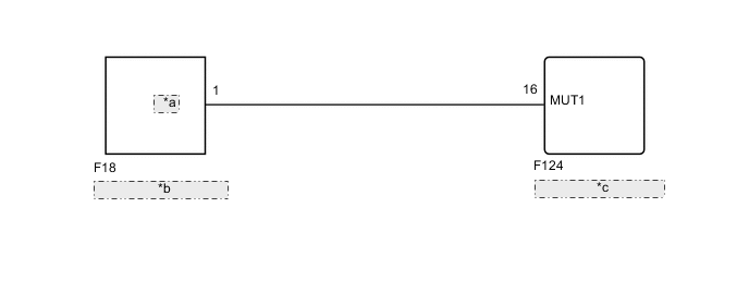
| *a | MUTE |
| *b | Stereo Component Amplifier Assembly |
| *c | Radio and Display Receiver Assembly |
CAUTION / NOTICE / HINT
Tech Tips
When replacing the radio and display receiver assembly, it is necessary to perform the vehicle contract setting for Connected Services (w/ Connected Services Function).
PROCEDURE
-
CHECK STEREO COMPONENT AMPLIFIER ASSEMBLY
-
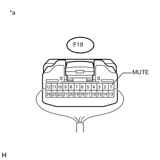
Text in Illustration *a Component with harness connected
(Stereo Component Amplifier Assembly)
Measure the voltage according to the value(s) in the table below.
Standard Voltage Tester Connection Condition Specified Condition F18-1 (MUTE) - Body ground Engine switch on (ACC), audio system playing → audio system changing modes 2.0 V or higher → Below 1 V
OK 
PROCEED TO NEXT SUSPECTED AREA SHOWN IN PROBLEM SYMPTOMS TABLE Click here
NG 
-
-
CHECK HARNESS AND CONNECTOR (RADIO AND DISPLAY RECEIVER ASSEMBLY - STEREO COMPONENT AMPLIFIER ASSEMBLY)
-
Disconnect the F124 radio and display receiver assembly connector.
-
Disconnect the F18 stereo component amplifier assembly connector.
-
Measure the resistance according to the value(s) in the table below.
Standard Resistance Tester Connection Condition Specified Condition F124-16 (MUT1) - F18-1 (MUTE) Always Below 1 Ω F124-16 (MUT1) - Body ground Always 10 kΩ or higher
NG
REPAIR OR REPLACE HARNESS OR CONNECTOR
OK
-
-
CHECK STEREO COMPONENT AMPLIFIER ASSEMBLY (OUTPUT SIGNAL)
-
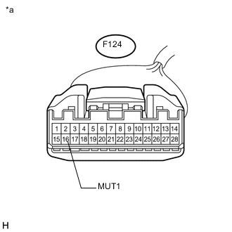
Text in Illustration *a Front view of wire harness connector
(to Radio and Display Receiver Assembly)
Measure the voltage according to the value(s) in the table below.
Standard Voltage Tester Connection Condition Specified Condition F124-16 (MUT1) - Body ground Engine switch on (ACC), audio system playing 2.0 V or higher
OK
REPLACE RADIO AND DISPLAY RECEIVER ASSEMBLY Click here
NG
REPLACE STEREO COMPONENT AMPLIFIER ASSEMBLY Click here
-