| DTC Code | DTC Name |
|---|---|
| B1579 | Voice Recognition Microphone Disconnected |
DESCRIPTION
The radio and display receiver assembly and map light assembly (telephone microphone assembly) are connected to each other using the microphone connection detection signal lines.
This DTC is stored when a microphone connection detection signal line is disconnected.
| DTC Code | DTC Detection Condition | Trouble Area |
|---|---|---|
| B1579 | Telephone microphone signal is lost. |
|
WIRING DIAGRAM
CAUTION / NOTICE / HINT
When replacing the radio and display receiver assembly, it is necessary to perform the vehicle contract setting for Connected Services (w/ Connected Services Function).
PROCEDURE
- Click here
CHECK RADIO AND DISPLAY RECEIVER ASSEMBLY
-
Measure the resistance according to the value(s) in the table below.
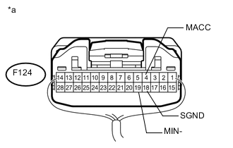
Standard Resistance Tester Connection Condition Specified Condition F124-18 (SGND) - Body ground Always Below 1 Ω F124-19 (MIN-) - Body ground Always Below 1 Ω -
Measure the voltage according to the value(s) in the table below.
Standard Voltage Tester Connection Switch Condition Specified Condition F124-4 (MACC) - Body ground Engine switch on (ACC) 4 to 6 V Table 2. Text in Illustration *a Component with harness connected
(Radio and Display Receiver Assembly)
- OKClick here
- NG
REPLACE RADIO AND DISPLAY RECEIVER ASSEMBLY (Click here)
-
- Click here
CHECK HARNESS AND CONNECTOR (RADIO AND DISPLAY RECEIVER ASSEMBLY - MAP LIGHT ASSEMBLY)
-
Disconnect the F124 radio and display receiver assembly connector.
-
Disconnect the R7 map light assembly connector.
-
Measure the resistance according to the value(s) in the table below.
Standard Resistance Tester Connection Condition Specified Condition F124-4 (MACC) - R7-25 (ACC) Always Below 1 Ω F124-5 (MIN+) - R7-27 (MI1+) Always Below 1 Ω F124-19 (MIN-) - R7-26 (MIC-) Always Below 1 Ω F124-6 (SNS2) - R7-20 (SNS2) Always Below 1 Ω F124-4 (MACC) - Body ground Always 10 kΩ or higher F124-5 (MIN+) - Body ground Always 10 kΩ or higher F124-19 (MIN-) - Body ground Always 10 kΩ or higher F124-18 (SGND) - Body ground Always 10 kΩ or higher F124-6 (SNS2) - Body ground Always 10 kΩ or higher
- OKClick here
- NG
REPAIR OR REPLACE HARNESS OR CONNECTOR
-
- Click here
CHECK TELEPHONE MICROPHONE ASSEMBLY
-
Replace the telephone microphone assembly with a known good one (Click here).
-
Clear the DTCs (Click here).
-
Check for DTCs (Click here).
OK No DTCs are output.
- OK
END (TELEPHONE MICROPHONE ASSEMBLY IS DEFECTIVE)
- NG
REPLACE MAP LIGHT ASSEMBLY (Click here)
-