VEHICLE STABILITY CONTROL SYSTEM, Diagnostic DTC:C1380
| DTC Code | DTC Name |
|---|---|
| C1380 | Stop Light Control Relay Malfunction |
DESCRIPTION
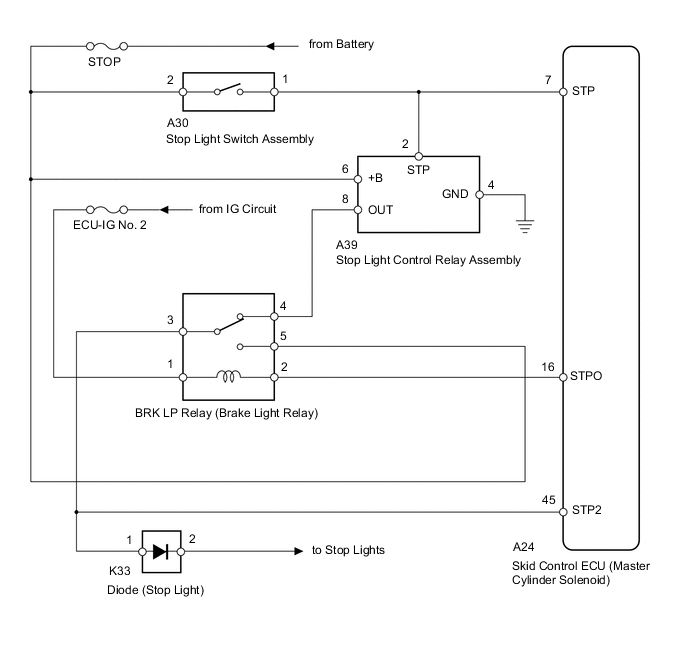
Upon receiving the hill-start assist control operating signal from the skid control ECU (master cylinder solenoid), the relay contact turns on and the stop light comes on.
| DTC Code | DTC Detection Condition | Trouble Area |
|---|---|---|
| C1380 | Either condition is met:
|
|
WIRING DIAGRAM
CAUTION / NOTICE / HINT
Note
-
After replacing the master cylinder solenoid, perform zero point calibration and store the system information Click here.
-
Inspect the fuses for circuits related to this system before performing the following inspection procedure.
Tech Tips
When DTC C1425 is output together with DTC C1380, inspect and repair the trouble areas indicated by DTC C1425 first Click here.
PROCEDURE
-
CHECK STOP LIGHT OPERATION
-
Check that the stop lights come on when the brake pedal is depressed and go off when the brake pedal is released.
OK Condition Illumination Condition Brake pedal depressed On Brake pedal released Off
NG 
CHECK HARNESS AND CONNECTOR (+B/GND TERMINAL) Click here
OK 
-
-
READ VALUE USING GTS (STOP LIGHT SW)
-
Turn the ignition switch off.
-
Connect the GTS to the DLC3.
-
Turn the ignition switch to ON.
-
Turn the GTS on.
-
Enter the following menus: Chassis / ABS/VSC/TRC / Data List.
ABS/VSC/TRC Tester Display Measurement Item/Range Normal Condition Diagnostic Note Stop Light SW Stop light switch / ON or OFF ON: Brake pedal depressed
OFF: Brake pedal released
- -
Check that the stop light switch condition observed on the GTS changes according to brake pedal operation.
OK The GTS displays ON and OFF according to brake pedal operation.
NG
CHECK HARNESS AND CONNECTOR (STP TERMINAL) Click here
OK
-
-
PERFORM ACTIVE TEST USING GTS (STOP LIGHT RELAY)
-
Turn the ignition switch off.
-
Connect the GTS to the DLC3.
-
Turn the ignition switch to ON.
-
Turn the GTS on.
-
Enter the following menus: Chassis / ABS/VSC/TRC / Active Test.
ABS/VSC/TRC Tester Display Test Part Control Range Diagnostic Note Stop Light Relay BRK LP relay (Brake light relay) Relay ON/OFF Observe the stop lights (the stop lights do not come on for 2 to 5 seconds). -
While performing the Active Test, check the illumination condition of the stop lights and "Stop Light Relay Output" in the Data List.
ABS/VSC/TRC Tester Display Measurement Item/Range Normal Condition Diagnostic Note Stop Light Relay Output BRK LP relay (Brake light relay) output / ON or OFF ON: Relay output on (Stop lights on)
OFF: Relay output off (Stop lights off)
- Result Result Proceed to When Active Test performed, Data List item changes between ON and OFF and stop lights turn on and off A When Active Test performed, Data List item changes between ON and OFF, but stop lights do not turn on B
B
INSPECT BRK LP RELAY Click here
A
-
-
CHECK HARNESS AND CONNECTOR (STP2 TERMINAL)
-
Turn the ignition switch off.
-
Disconnect the skid control ECU (master cylinder solenoid) connector.
-
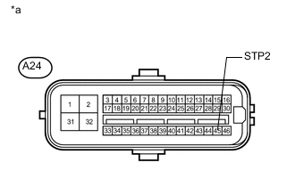
Text in Illustration *a Front view of wire harness connector
(to Skid Control ECU [Master Cylinder Solenoid])
Measure the voltage according to the value(s) in the table below.
Standard Voltage Tester Connection Condition Specified Condition A24-45 (STP2) - Body ground Brake pedal depressed 8 to 14 V Brake pedal released Below 1.5 V
NG 
REPAIR OR REPLACE HARNESS OR CONNECTOR
OK
-
-
RECONFIRM DTC
-
Clear the DTCs Click here.
-
Turn the ignition switch off.
-
Start the engine.
-
Perform a road test.
-
Check if the same DTC is output Click here.
Result Result Proceed to DTC is not output A DTC is output (for LHD) B DTC is output (for RHD) C
A
CHECK FOR INTERMITTENT PROBLEMS Click here
B
REPLACE MASTER CYLINDER SOLENOID Click here
C
REPLACE MASTER CYLINDER SOLENOID Click here
-
-
CHECK HARNESS AND CONNECTOR (+B/GND TERMINAL)
-
Turn the ignition switch off.
-
Disconnect the stop light control relay assembly connector.
-
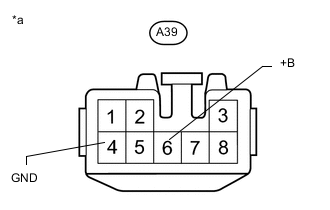
Text in Illustration *a Front view of wire harness connector
(to Stop Light Control Relay Assembly)
Measure the voltage according to the value(s) in the table below.
Standard Voltage Tester Connection Condition Specified Condition A39-6 (+B) - Body ground Always 11 to 14 V -
Measure the resistance according to the value(s) in the table below.
Standard Resistance Tester Connection Condition Specified Condition A39-4 (GND) - Body ground Always Below 1 Ω
NG
REPAIR OR REPLACE HARNESS OR CONNECTOR
OK
-
-
CHECK HARNESS AND CONNECTOR (STP TERMINAL)
-
Turn the ignition switch off.
-
Disconnect the stop light control relay assembly connector.
-
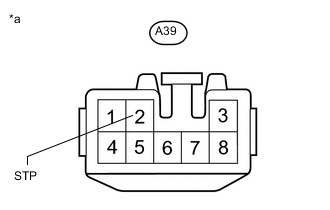
Text in Illustration *a Front view of wire harness connector
(to Stop Light Control Relay Assembly)
Measure the voltage according to the value(s) in the table below.
Standard Voltage Tester Connection Condition Specified Condition A39-2 (STP) - Body ground Brake pedal depressed 8 to 14 V Brake pedal released Below 1.5 V
NG
REPAIR OR REPLACE HARNESS OR CONNECTOR
OK
-
-
INSPECT BRK LP RELAY
-
Remove the BRK LP relay (brake light relay) from the engine room relay block.
-
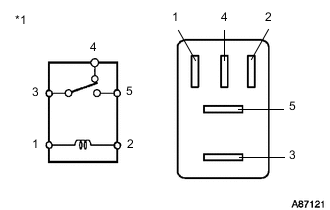
Text in Illustration *1 BRK LP Relay (Brake Light Relay) Measure the resistance according to the value(s) in the table below.
Standard Resistance Tester Connection Condition Specified Condition 3 - 4 Battery positive voltage is applied to terminal 1 and battery negative voltage is applied to terminal 2 10 kΩ or higher Battery positive voltage is not applied to terminal 1 and battery negative voltage is not applied to terminal 2 Below 1 Ω 3 - 5 Battery positive voltage is applied to terminal 1 and battery negative voltage is applied to terminal 2 Below 1 Ω Battery positive voltage is not applied to terminal 1 and battery negative voltage is not applied to terminal 2 10 kΩ or higher
NG
REPLACE BRAKE LIGHT RELAY
OK
-
-
CHECK HARNESS AND CONNECTOR (STOP LIGHT CONTROL RELAY - BRK LP RELAY)
-
Turn the ignition switch off.
-
Disconnect the A39 stop light control relay assembly connector.
-
Remove the BRK LP relay (brake light relay) from the engine room relay block.
-
Measure the resistance according to the value(s) in the table below.
Standard Resistance Tester Connection Condition Specified Condition A39-8 (OUT) - Engine room relay block BRK LP relay (brake light relay) terminal 4 Always Below 1 Ω A39-8 (OUT) - Body ground Always 10 kΩ or higher
NG
REPAIR OR REPLACE HARNESS OR CONNECTOR
OK
-
-
CHECK HARNESS AND CONNECTOR (STOP LIGHT POWER SOURCE TERMINAL)
-
Remove the BRK LP relay (brake light relay) from the engine room relay block.
-
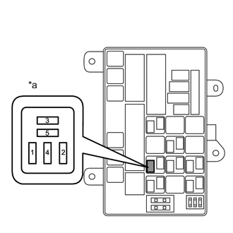
Text in Illustration *a Component without BRK LP Relay (Brake Light Relay)
(Engine Room Relay Block)
Measure the voltage according to the value(s) in the table below.
Standard Voltage Tester Connection Condition Specified Condition 4 - Body ground Brake pedal depressed 8 to 14 V Brake pedal released Below 1.5 V
OK
REPAIR OR REPLACE HARNESS OR CONNECTOR (ENGINE ROOM RELAY BLOCK BRK LP RELAY TERMINAL 3 CIRCUIT)
NG
REPLACE STOP LIGHT CONTROL RELAY ASSEMBLY
-
-
CHECK HARNESS AND CONNECTOR (STP TERMINAL)
-
Turn the ignition switch off.
-
Disconnect the skid control ECU (master cylinder solenoid) connector.
-
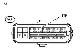
Text in Illustration *a Front view of wire harness connector
(to Skid Control ECU [Master Cylinder Solenoid])
Measure the voltage according to the value(s) in the table below.
Standard Voltage Tester Connection Condition Specified Condition A24-7 (STP) - Body ground Brake pedal depressed 8 to 14 V Brake pedal released Below 1.5 V Result Result Proceed to NG A OK (for LHD) B OK (for RHD) C
A
REPAIR OR REPLACE HARNESS OR CONNECTOR
B
REPLACE MASTER CYLINDER SOLENOID Click here
C
REPLACE MASTER CYLINDER SOLENOID Click here
-
-
INSPECT BRK LP RELAY
-
Remove the BRK LP relay (brake light relay) from the engine room relay block.
-
Text in Illustration *1 BRK LP Relay (Brake Light Relay) Measure the resistance according to the value(s) in the table below.
Standard Resistance Tester Connection Condition Specified Condition 3 - 4 Battery positive voltage is applied to terminal 1 and battery negative voltage is applied to terminal 2 10 kΩ or higher Battery positive voltage is not applied to terminal 1 and battery negative voltage is not applied to terminal 2 Below 1 Ω 3 - 5 Battery positive voltage is applied to terminal 1 and battery negative voltage is applied to terminal 2 Below 1 Ω Battery positive voltage is not applied to terminal 1 and battery negative voltage is not applied to terminal 2 10 kΩ or higher
NG
REPLACE BRAKE LIGHT RELAY
OK
-
-
CHECK HARNESS AND CONNECTOR (BRK LP RELAY POWER SOURCE TERMINAL)
-
Remove the BRK LP relay (brake light relay) from the engine room relay block.
-
Text in Illustration *a Component without BRK LP relay (Brake Light Relay)
(Engine Room Relay Block)
Measure the voltage according to the value(s) in the table below.
Standard Voltage Tester Connection Condition Specified Condition 1 - Body ground Ignition switch ON 8 to 14 V 5 - Body ground Always 11 to 14 V
NG
REPAIR OR REPLACE HARNESS OR CONNECTOR
OK
-
-
CHECK HARNESS AND CONNECTOR (STPO TERMINAL)
-
Turn the ignition switch off.
-
Disconnect the skid control ECU (master cylinder solenoid) connector.
-
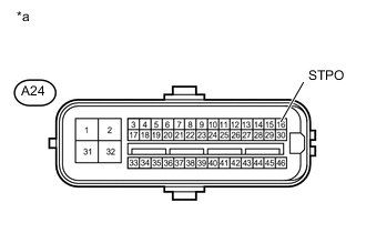
Text in Illustration *a Front view of wire harness connector
(to Skid Control ECU [Master Cylinder Solenoid])
Measure the voltage according to the value(s) in the table below.
Standard Voltage Tester Connection Switch Condition Specified Condition A24-16 (STPO) - Body ground Ignition switch ON 11 to 14 V
NG
REPAIR OR REPLACE HARNESS OR CONNECTOR
OK
-
-
RECONFIRM DTC
-
Clear the DTCs Click here.
-
Turn the ignition switch off.
-
Check if the same DTC is output Click here.
Result Result Proceed to DTC is not output A DTC is output (for LHD) B DTC is output (for RHD) C
A
CHECK FOR INTERMITTENT PROBLEMS Click here
B
REPLACE MASTER CYLINDER SOLENOID Click here
C
REPLACE MASTER CYLINDER SOLENOID Click here
-