TIRE PRESSURE WARNING SYSTEM Tire Pressure Warning Light Circuit
DESCRIPTION
If the ECU detects trouble, the tire pressure warning light blinks (illuminates after blinking for 1 minute) and tire pressure monitoring is canceled at the same time. At this time, the ECU stores a DTC in the memory.
Connect terminals TC and CG of the DLC3 to make the tire pressure warning light blink and output the DTC.
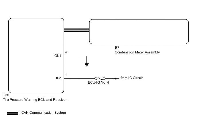
WIRING DIAGRAM
CAUTION / NOTICE / HINT
Note
-
When replacing the tire pressure warning ECU and receiver, read the transmitter IDs stored in the old ECU using the GTS and write them down before removal.
-
It is necessary to perform initialization (See page ) after registration Click here of the transmitter IDs into the tire pressure warning ECU and receiver if the ECU has been replaced.
PROCEDURE
-
CHECK CAN COMMUNICATION LINE
-
Turn the engine switch off.
-
Connect the GTS to the DLC3.
-
Turn the engine switch on (IG) and turn the GTS on.
-
Enter the following menus: "CAN Bus Check" from the "System Select" screen.
-
Check the CAN communication system (for LHD: See page , for RHD: Click here.
OK The CAN communication system is normal. Result Result Proceed to OK A NG (for LHD) B NG (for RHD) C
B 
GO TO CAN COMMUNICATION SYSTEM Click here
C
GO TO CAN COMMUNICATION SYSTEM Click here
A 
-
-
CHECK TIRE PRESSURE WARNING LIGHT CONDITION
-
Check for tire pressure warning light condition.
Result Result Proceed to Tire pressure warning light does not illuminate despite tire pressure decreasing A Tire pressure warning light remains illuminated (goes off during initial check) B Tire pressure warning light remains illuminated (illuminates during initial check) C
B 
CHECK IF TIRE PRESSURE WARNING ECU AND RECEIVER CONNECTOR IS SECURELY CONNECTED Click here
C
GO TO PROBLEM SYMPTOMS TABLE Click here
A
-
-
PERFORM INSPECTION CHECK NECESSARY FOR SYMPTOM
Note
If the following checks in the Suspected Area column of the Problem Symptoms Table have not been performed, make sure to perform the following checks before proceeding Click here.
If the items below are normal, proceed to the next step.
-
Initialization
-
Check Data List (ID Tire Inflation Pressure)
-
ID code check (Registration)
NEXT
-
-
CHECK OPERATION OF TIRE PRESSURE WARNING LIGHT (ACTIVE TEST)
-
Turn the engine switch off.
-
Connect the GTS to the DLC3.
-
Turn the engine switch on (IG) and turn the GTS on.
-
Enter the following menus: Body Electrical / Combination Meter / Active Test.
-
Check the condition of the tire pressure warning light by operating the GTS.
Combination Meter Tester Display Test Part Control Range Indicat. Tire Pressure Warning System Tire Pressure Warning Light OFF or ON OK The warning light turns on when operating the GTS.
OK
REPLACE TIRE PRESSURE WARNING ECU AND RECEIVER Click here
NG
GO TO METER / GAUGE SYSTEM Click here
-
-
CHECK IF TIRE PRESSURE WARNING ECU AND RECEIVER CONNECTOR IS SECURELY CONNECTED
-
Check if the tire pressure warning ECU and receiver connector is securely connected.
OK The connector is securely connected.
NG
CONNECT CONNECTOR TO TIRE PRESSURE WARNING ECU AND RECEIVER CORRECTLY
OK
-
-
CHECK HARNESS AND CONNECTOR (TIRE PRESSURE WARNING ECU AND RECEIVER - BATTERY AND BODY GROUND)
-
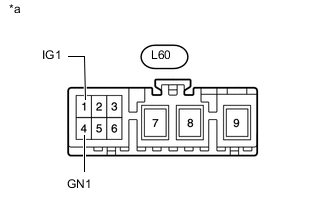
Text in Illustration *a Front view of wire harness connector
(to Tire Pressure Warning ECU and Receiver)
Disconnect the tire pressure warning ECU and receiver L60 connector.
-
Measure the voltage according to the value(s) in the table below.
Standard Voltage Tester Connection Switch Condition Specified Condition L60-1 (IG1) - Body ground Engine switch on (IG) 10 to 16 V Engine switch off Below 1 V -
Measure the resistance according to the value(s) in the table below.
Standard Resistance Tester Connection Condition Specified Condition L60-4 (GN1) - Body ground Always Below 1 Ω
OK
REPLACE TIRE PRESSURE WARNING ECU AND RECEIVER Click here
NG
REPAIR OR REPLACE HARNESS OR CONNECTOR
-