PROCEDURE
- Click here
INSTALL GENERATOR ASSEMBLY
-
Temporarily install the generator with the 2 stud bolts.
-
Using an E7 "TORX" socket wrench, tighten the 2 stud bolts.
6.0 N*m 61 kgf*cm 53 in.*lbf -
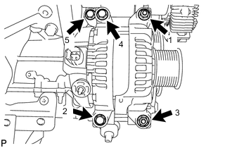
Install the 2 nuts and 3 bolts in the order shown in the illustration.
21 N*m 214 kgf*cm 15 ft.*lbf -
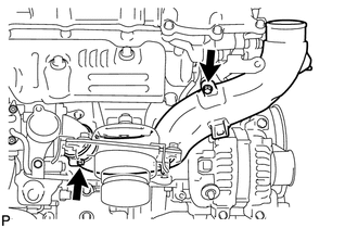
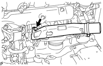
Install the the No. 1 intake air connector pipe to the No. 1 inlet compressor elbow.
-
Install the No. 1 intake air connector bracket with the 2 bolts.
21 N*m 214 kgf*cm 15 ft.*lbf -
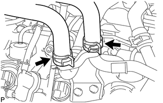
Install the bolt to the No. 1 intake air connector pipe. Then tighten the hose clamp.
for bolt 21 N*m 214 kgf*cm 15 ft.*lbf for hose clamp 6.0 N*m 61 kgf*cm 53 in.*lbf -
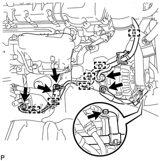
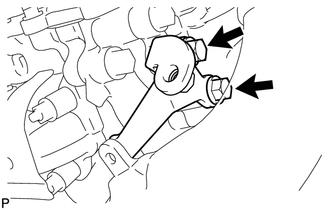
Connect the wire harness bracket to the belt tensioner with the bolt.
13 N*m 133 kgf*cm 10 ft.*lbf -
130 A Type and 150 A Type:
Connect the generator wire with the nut.
9.8 N*m 100 kgf*cm 87 in.*lbf -
180 A Type:
Connect the generator wire with the nut.
12 N*m 122 kgf*cm 9 ft.*lbf -
Install the terminal cap.
-
Connect the 6 wire harness clamps.
-
Connect the 4 connectors.
-
- Click here
INSTALL NO. 1 AIR TUBE ASSEMBLY
-
Apply a light coat of washer fluid to a new O-ring and install it to the No. 1 air tube.
-
Install the No. 1 air tube with the bolt.
21 N*m 214 kgf*cm 15 ft.*lbf
-
- Click here
INSTALL NO. 1 AIR CLEANER PIPE SUB-ASSEMBLY
- Click here
INSTALL HEATER WATER PIPE SUB-ASSEMBLY (w/ Viscous Heater)
- Click here
INSTALL NO. 3 AIR TUBE
- Click here
INSTALL NO. 1 AIR HOSE
- Click here
INSTALL INTAKE AIR CONNECTOR
- Click here
TEMPORARILY INSTALL NO. 1 AIR CLEANER HOSE
- Click here
INSTALL AIR CLEANER CAP SUB-ASSEMBLY
- Click here
INSTALL NO. 2 ENGINE OIL LEVEL DIPSTICK GUIDE
- Click here
CONNECT WATER HOSE SUB-ASSEMBLY (w/ Viscous Heater)
-
Connect the 2 water hoses.
-
- Click here
INSTALL NO. 2 COOL AIR INLET (w/o Intercooler)
- Click here
INSTALL NO. 1 COOL AIR INLET (w/o Intercooler)
- Click here
INSTALL INTERCOOLER ASSEMBLY (w/ Intercooler)
- Click here
INSTALL V-RIBBED BELT
- Click here
INSTALL NO. 3 IDLER PULLEY (w/ Viscous Heater)
- Click here
INSTALL NO. 1 IDLER PULLEY (w/ Viscous Heater)
- Click here
INSTALL V-RIBBED BELT (w/ Viscous Heater)
- Click here
CONNECT CABLE TO NEGATIVE BATTERY TERMINAL
Note:When disconnecting the cable, some systems need to be initialized after the cable is reconnected (Click here).
- Click here
ADD ENGINE COOLANT
- Click here
INSPECT FOR COOLANT LEAK
- Click here
INSTALL FRONT FENDER APRON SEAL REAR RH
- Click here
INSTALL FRONT FENDER APRON SEAL FRONT RH
- Click here
INSTALL NO. 1 ENGINE UNDER COVER SUB-ASSEMBLY
- Click here
INSTALL FRONT FENDER SPLASH SHIELD SUB-ASSEMBLY LH
- Click here
INSTALL FRONT FENDER SPLASH SHIELD SUB-ASSEMBLY RH