MULTI-TERRAIN MONITOR SYSTEM Image from Camera for Multi-terrain Monitor is Abnormal
DESCRIPTION
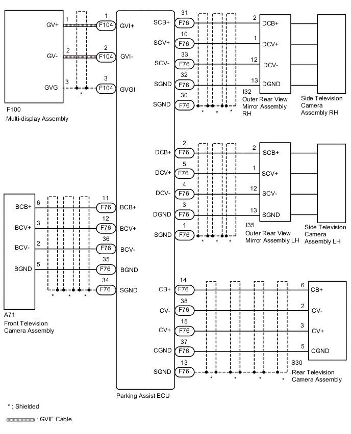
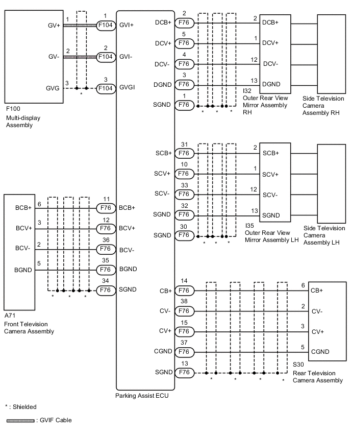
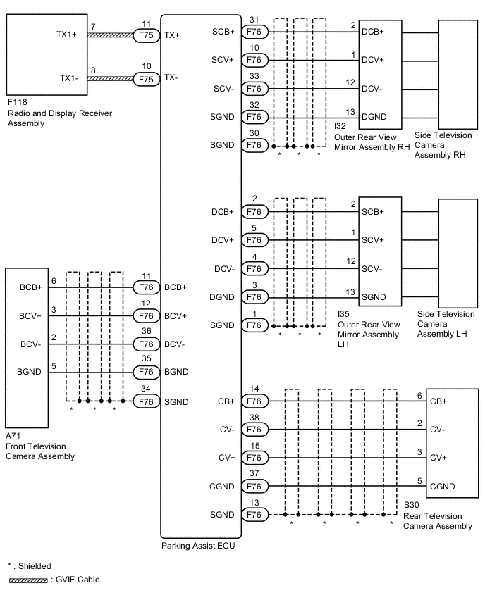
The video signal from the each television camera is transmitted to the multi-display assembly*1 or radio and display receiver assembly*2.
-
*1: for Multi-media Module Receiver Type
-
*2: for Radio and Display Type
WIRING DIAGRAM
-
for LHD, Multi-media Module Receiver Type:
-
for RHD, Multi-media Module Receiver Type:
-
for Radio and Display Type:
CAUTION / NOTICE / HINT
Note
-
When "!" mark is displayed on the multi-display after disconnecting the cable from the negative (-) battery terminal, correct the steering angle neutral point Click here.
-
Depending on the parts that are replaced or operations that are performed during vehicle inspection or maintenance, calibration of other systems as well as the multi-terrain monitor system may be needed Click here.
Tech Tips
Images may be unclear even in normal conditions if:-
Electrical devices are used in the cabin (noise may occur in the image).
-
The camera lens is frosted over (the image immediately after turning the engine switch on (IG) may be blurred or darker than normal).
-
The camera lens is dirty with snow, mud, etc.
-
A strong beam of light, such as a sunbeam or headlight, hits the camera.
-
It is too dark around the camera (at night, etc.).
-
The ambient temperature around the camera is either too high or too low.
-
The vehicle is tilted at a steep angle.
-
The television camera assembly lens is scratched.
-
The television camera assembly lens has drops of water on it or the humidity is high.
-
When the camera is used under fluorescent lights, sodium lights, or mercury lights, etc., the lights and the illuminated area may appear to flicker.
PROCEDURE
-
CHECK MULTI-TERRAIN MONITOR SYSTEM
-
Check if the same malfunction occurs when the multi-terrain monitor screen is displayed.
Result Result Proceed to Rear view screen is not displayed. A Front view screen is not displayed. B Passenger side monitor screen is not displayed. C Driver side monitor screen is not displayed. D Multi-terrain monitor screen is not displayed. E
B 
CHECK HARNESS AND CONNECTOR (PARKING ASSIST ECU - FRONT TELEVISION CAMERA ASSEMBLY) Click here
C
CHECK HARNESS AND CONNECTOR (PARKING ASSIST ECU - OUTER REAR VIEW MIRROR ASSEMBLY) Click here
D
CHECK HARNESS AND CONNECTOR (PARKING ASSIST ECU - OUTER REAR VIEW MIRROR ASSEMBLY) Click here
E
READ VALUE USING GTS Click here
A 
-
-
CHECK HARNESS AND CONNECTOR (PARKING ASSIST ECU - REAR TELEVISION CAMERA ASSEMBLY)
-
Disconnect the F76 parking assist ECU connector.
-
Disconnect the S30 rear television camera assembly connector.
-
Measure the resistance according to the value(s) in the table below.
Standard Resistance Tester Connection Condition Specified Condition F76-38 (CV-) - S30-2 (CV-) Always Below 1 Ω F76-15 (CV+) - S30-3 (CV+) Always Below 1 Ω F76-14 (CB+) - S30-6 (CB+) Always Below 1 Ω F76-37 (CGND) - S30-5 (CGND) Always Below 1 Ω F76-13 (SGND) - Body ground Always Below 1 Ω F76-38 (CV-) or S30-2 (CV-) - Body ground Always 10 kΩ or higher F76-15 (CV+) or S30-3 (CV+) - Body ground Always 10 kΩ or higher F76-14 (CB+) or S30-6 (CB+) - Body ground Always 10 kΩ or higher F76-37 (CGND) or S30-5 (CGND) - Body ground Always 10 kΩ or higher
NG 
REPAIR OR REPLACE HARNESS OR CONNECTOR
OK
-
-
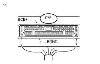
CHECK PARKING ASSIST ECU (CB+, CGND)
-
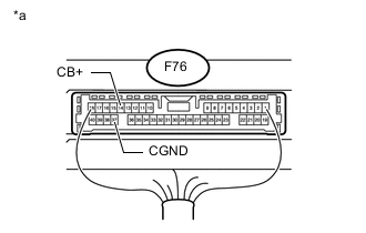
Text in Illustration *a Component with harness connected
(Parking Assist ECU)
Measure the resistance according to the value(s) in the table below.
Standard Resistance Tester Connection Condition Specified Condition F76-37 (CGND) - Body ground Always Below 1 Ω -
Measure the voltage according to the value(s) in the table below.
Standard Voltage Tester Connection Switch Condition Specified Condition F76-14 (CB+) - F76-37 (CGND) Engine switch on (IG) 5.5 to 7.05 V
NG
REPLACE PARKING ASSIST ECU Click here
OK
-
-
CHECK REAR TELEVISION CAMERA ASSEMBLY (CV+, CGND)
-
Check the waveform of the rear television camera assembly using an oscilloscope.

Text in Illustration *a Component with harness connected
(Parking Assist ECU)
*b Waveform A *c Waveform B *d Synchronization Signal *e Video Waveform - - Tech Tips
The video waveform changes according to the image sent by the rear television camera assembly.
Item Content Terminal No. (Symbol) F76-15 (CV+) - F76-37 (CGND) Tool Setting 200 mV/DIV., 50 μsec./DIV. Condition
-
Waveform A: Engine switch on (IG), shift lever in R and camera lens is not covered, displaying an image
-
Waveform B: Engine switch on (IG), shift lever in R and camera lens is covered, blacking out the screen
OK Waveform is as shown in the illustration. -
OK
REPLACE PARKING ASSIST ECU Click here
NG
REPLACE REAR TELEVISION CAMERA ASSEMBLY Click here
-
-
CHECK HARNESS AND CONNECTOR (PARKING ASSIST ECU - FRONT TELEVISION CAMERA ASSEMBLY)
-
Disconnect the F76 parking assist ECU connector.
-
Disconnect the A71 front television camera assembly connector.
-
Measure the resistance according to the value(s) in the table below.
Standard Resistance Tester Connection Condition Specified Condition F76-36 (BCV-) - A71-2 (BCV-) Always Below 1 Ω F76-12 (BCV+) - A71-3 (BCV+) Always Below 1 Ω F76-35 (BGND) - A71-5 (BGND) Always Below 1 Ω F76-11 (BCB+) - A71-6 (BCB+) Always Always F76-34 (SGND) - Body ground Always Always F76-36 (BCV-) - Body ground Always 10 kΩ or higher F76-12 (BCV+) - Body ground Always 10 kΩ or higher F76-35 (BGND) - Body ground Always 10 kΩ or higher F76-11 (BCB+) - Body ground Always 10 kΩ or higher
NG
REPAIR OR REPLACE HARNESS OR CONNECTOR
OK
-
-
CHECK PARKING ASSIST ECU (BCB+, BGND)
-
Text in Illustration *a Component with harness connected
(Parking Assist ECU)
Measure the resistance according to the value(s) in the table below.
Standard Resistance Tester Connection Condition Specified Condition F76-35 (BGND) - Body ground Always Below 1 Ω -
Measure the voltage according to the value(s) in the table below.
Standard Voltage Tester Connection Switch Condition Specified Condition F76-11 (BCB+) - F76-35 (BGND) Engine switch on (IG) 5.5 to 7.05 V
NG
REPLACE PARKING ASSIST ECU Click here
OK
-
-
CHECK FRONT TELEVISION CAMERA ASSEMBLY (BCV+, BGND)
-
Check the ware form of the front television camera assembly using an oscilloscope.
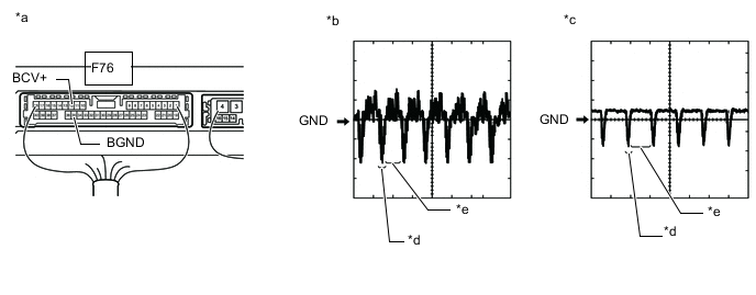
Text in Illustration *a Component with harness connected
(Parking Assist ECU)
*b Waveform A *c Waveform B *d Synchronization Signal *e Video Waveform - - Tech Tips
The video waveform changes according to the image sent by the front television camera assembly.
Item Content Terminal No. (Symbol) F76-12 (BCV+) - F76-35 (BGND) Tool Setting 200 mV/DIV., 50 μsec./DIV. Condition
-
Waveform A: Engine switch on (IG), main switch assembly (multi-terrain monitor main switch) on and camera lens is not covered, displaying an image
-
Waveform B: Engine switch on (IG), main switch assembly (multi-terrain monitor main switch) on and camera lens is covered, blacking out the screen
OK Waveform is as shown in the illustration. -
OK
REPLACE PARKING ASSIST ECU Click here
NG
REPLACE FRONT TELEVISION CAMERA ASSEMBLY Click here
-
-
CHECK HARNESS AND CONNECTOR (PARKING ASSIST ECU - OUTER REAR VIEW MIRROR ASSEMBLY)
-
Disconnect the F76 parking assist ECU connector.
-
Disconnect the I32*1 or I35*2 outer rear view mirror assembly connector.
-
*1: for LHD
-
*2: for RHD
-
-
Measure the resistance according to the value(s) in the table below.
Standard Resistance for LHD Tester Connection Condition Specified Condition F76-33 (SCV-) - I32-12 (DCV-) Always Below 1 Ω F76-10 (SCV+) - I32-1 (DCV+) Always Below 1 Ω F76-32 (SGND) - I32-13 (DGND) Always Below 1 Ω F76-31 (SCB+) - I32-2 (DCB+) Always Below 1 Ω F76-30 (SGND) - Body ground Always Below 1 Ω F76-33 (SCV-) - Body ground Always 10 kΩ or higher F76-10 (SCV+) - Body ground Always 10 kΩ or higher F76-32 (SGND) - Body ground Always 10 kΩ or higher F76-31 (SCB+) - Body ground Always 10 kΩ or higher for RHD Tester Connection Condition Specified Condition F76-33 (SCV-) - I35-12 (SCV-) Always Below 1 Ω F76-10 (SCV+) - I35-1 (SCV+) Always Below 1 Ω F76-32 (SGND) - I35-13 (SGND) Always Below 1 Ω F76-31 (SCB+) - I35-2 (SCB+) Always Below 1 Ω F76-30 (SGND) - Body ground Always Below 1 Ω F76-33 (SCV-) - Body ground Always 10 kΩ or higher F76-10 (SCV+) - Body ground Always 10 kΩ or higher F76-32 (SGND) - Body ground Always 10 kΩ or higher F76-31 (SCB+) - Body ground Always 10 kΩ or higher
NG
REPAIR OR REPLACE HARNESS OR CONNECTOR
OK
-
-
CHECK PARKING ASSIST ECU (SCB+, SGND)
-
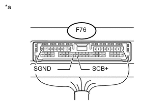
Text in Illustration *a Component with harness connected
(Parking Assist ECU)
Measure the resistance according to the value(s) in the table below.
Standard Resistance Tester Connection Condition Specified Condition F76-32 (SGND) - Body ground Always Below 1 Ω -
Measure the voltage according to the value(s) in the table below.
Standard Voltage Tester Connection Switch Condition Specified Condition F76-31 (SCB+) - F76-32 (SGND) Engine switch on (IG) 5.5 to 7.05 V
NG
REPLACE PARKING ASSIST ECU Click here
OK
-
-
CHECK SIDE TELEVISION CAMERA ASSEMBLY (SCV+, SGND)
-
Check the ware form of the side television camera assembly using an oscilloscope.

Text in Illustration *a Component with harness connected
(Parking Assist ECU)
*b Waveform A *c Waveform B *d Synchronization Signal *e Video Waveform - - Tech Tips
The video waveform changes according to the image sent by the side television camera assembly.
Item Content Terminal No. (Symbol) F76-10 (SCV+) - F76-32 (SGND) Tool Setting 200 mV/DIV., 50 μsec./DIV. Condition
-
Waveform A: Engine switch on (IG), main switch assembly (multi-terrain monitor main switch) on and camera lens is not covered, displaying an image
-
Waveform B: Engine switch on (IG), main switch assembly (multi-terrain monitor main switch) on and camera lens is covered, blacking out the screen
OK Waveform is as shown in the illustration. -
OK
REPLACE PARKING ASSIST ECU Click here
NG
-
-
CHECK SIDE TELEVISION CAMERA ASSEMBLY
-
for LHD:
Replace the side television camera assembly RH with a new or normally functioning one Click here.
-
for RHD:
Replace the side television camera assembly LH with a new or normally functioning one Click here.
-
Check if the same malfunction reoccurs when the multi-terrain monitor screen is displayed.
Result Result Proceed to Malfunction does not reoccur (returns to normal) A Malfunction reoccurs (for LHD) B Malfunction reoccurs (for RHD) B
A
END (SIDE TELEVISION CAMERA ASSEMBLY LH IS DEFECTIVE)
B
REPLACE OUTER REAR VIEW MIRROR ASSEMBLY RH Click here
C
REPLACE OUTER REAR VIEW MIRROR ASSEMBLY LH Click here
-
-
CHECK HARNESS AND CONNECTOR (PARKING ASSIST ECU - OUTER REAR VIEW MIRROR ASSEMBLY)
-
Disconnect the F76 parking assist ECU connector.
-
Disconnect the I35*1 or I32*2 outer rear view mirror assembly connector.
-
*1: for LHD
-
*2: for RHD
-
-
Measure the resistance according to the value(s) in the table below.
Standard Resistance for LHD Tester Connection Condition Specified Condition F76-4 (DCV-) - I35-12 (SCV-) Always Below 1 Ω F76-5 (DCV+) - I35-1 (SCV+) Always Below 1 Ω F76-3 (DGND) - I35-13 (SGND) Always Below 1 Ω F76-2 (DCB+) - I35-2 (SCB+) Always Below 1 Ω F76-1 (SGND) - Body ground Always Below 1 Ω F76-4 (DCV-) - Body ground Always 10 kΩ or higher F76-5 (DCV+) - Body ground Always 10 kΩ or higher F76-3 (DGND) - Body ground Always 10 kΩ or higher F76-2 (DCB+) - Body ground Always 10 kΩ or higher for RHD Tester Connection Condition Specified Condition F76-4 (DCV-) - I32-12 (DCV-) Always Below 1 Ω F76-5 (DCV+) - I32-1 (DCV+) Always Below 1 Ω F76-3 (DGND) - I32-13 (DGND) Always Below 1 Ω F76-2 (DCB+) - I32-2 (DCB+) Always Below 1 Ω F76-1 (SGND) - Body ground Always Below 1 Ω F76-4 (DCV-) - Body ground Always 10 kΩ or higher F76-5 (DCV+) - Body ground Always 10 kΩ or higher F76-3 (DGND) - Body ground Always 10 kΩ or higher F76-2 (DCB+) - Body ground Always 10 kΩ or higher
NG
REPAIR OR REPLACE HARNESS OR CONNECTOR
OK
-
-
CHECK PARKING ASSIST ECU (DCB+, DGND)
-

Text in Illustration *a Component with harness connected
(Parking Assist ECU)
Measure the resistance according to the value(s) in the table below.
Standard Resistance Tester Connection Condition Specified Condition F76-3 (DGND) - Body ground Always Below 1 Ω -
Measure the voltage according to the value(s) in the table below.
Standard Voltage Tester Connection Switch Condition Specified Condition F76-2 (DCB+) - F76-3 (DGND) Engine switch on (IG) 5.5 to 7.05 V
NG
REPLACE PARKING ASSIST ECU Click here
OK
-
-
CHECK SIDE TELEVISION CAMERA ASSEMBLY (SCV+, SGND)
-
Check the ware form of the side television camera assembly using an oscilloscope.
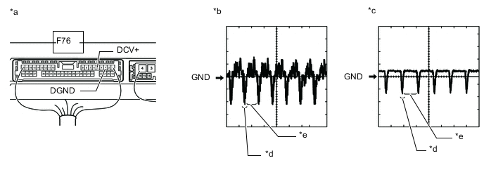
Text in Illustration *a Component with harness connected
(Parking Assist ECU)
*b Waveform A *c Waveform B *d Synchronization Signal *e Video Waveform - - Tech Tips
The video waveform changes according to the image sent by the side television camera assembly.
Item Content Terminal No. (Symbol) F76-5 (DCV+) - F76-3 (DGND) Tool Setting 200 mV/DIV., 50 μsec./DIV. Condition
-
Waveform A: Engine switch on (IG), main switch assembly (multi-terrain monitor main switch) on and camera lens is not covered, displaying an image
-
Waveform B: Engine switch on (IG), main switch assembly (multi-terrain monitor main switch) on and camera lens is covered, blacking out the screen
OK Waveform is as shown in the illustration. -
OK
REPLACE PARKING ASSIST ECU Click here
NG
-
-
CHECK SIDE TELEVISION CAMERA ASSEMBLY
-
for LHD:
Replace the side television camera assembly LH with a new or normally functioning one Click here.
-
for RHD:
Replace the side television camera assembly RH with a new or normally functioning one Click here.
-
Check if the same malfunction reoccurs when the multi-terrain monitor screen is displayed.
Result Result Proceed to Malfunction does not reoccur (returns to normal) A Malfunction reoccurs (for LHD) B Malfunction reoccurs (for RHD) B
A
END (SIDE TELEVISION CAMERA ASSEMBLY RH IS DEFECTIVE)
B
REPLACE OUTER REAR VIEW MIRROR ASSEMBLY LH Click here
C
REPLACE OUTER REAR VIEW MIRROR ASSEMBLY RH Click here
-
-
READ VALUE USING GTS
-
According to the display on the GTS, read the Data List. Click here.
Intelligent Parking Assist System / Back Guide Monitor Tester Display Measurement Item/Range Normal Condition Diagnostic Note Video Output Status Status of the video output status / OK or NG OK: Parking assist ECU is normal
NG: Parking assist ECU is abnormal
- OK OK is displayed. Result Result Proceed to OK A NG (for Multi-media Module Receiver Type) B NG (for Radio and Display Type) C
A
REPLACE PARKING ASSIST ECU Click here
C
CHECK HARNESS AND CONNECTOR (PARKING ASSIST ECU - RADIO AND DISPLAY RECEIVER ASSEMBLY) Click here
B
-
-
CHECK HARNESS AND CONNECTOR (PARKING ASSIST ECU - MULTI-DISPLAY [GVIF CABLE])
-
Replace the GVIF cable with a new or normally functioning one.
-
Check if the same malfunction reoccurs when the multi-terrain monitor screen is displayed.
Result Result Proceed to Malfunction does not reoccur (returns to normal) A Malfunction reoccurs B
A
END (GVIF CABLE IS DEFECTIVE)
B
-
-
CHECK MULTI-DISPLAY ASSEMBLY
-
Replace the multi-display assembly with a new or normally functioning one Click here.
-
Check if the same malfunction reoccurs when the multi-terrain monitor screen is displayed.
Result Result Proceed to Malfunction does not reoccur (returns to normal) A Malfunction reoccurs B
A
END (MULTI-DISPLAY ASSEMBLY IS DEFECTIVE)
B
REPLACE PARKING ASSIST ECU Click here
-
-
CHECK HARNESS AND CONNECTOR (PARKING ASSIST ECU - RADIO AND DISPLAY RECEIVER ASSEMBLY)
-
Disconnect the F75 parking assist ECU connector.
-
Disconnect the F118 radio and display receiver assembly connector.
-
Measure the resistance according to the value(s) in the table below.
Standard Resistance Tester Connection Condition Specified Condition F75-11 (TX+) - F118-7 (TX1+) Always Below 1 Ω F75-10 (TX-) - F118-8 (TX1-) Always Below 1 Ω F75-11 (TX+) - Body ground Always 10 kΩ or higher F75-10 (TX-) - Body ground Always 10 kΩ or higher
NG
REPAIR OR REPLACE HARNESS OR CONNECTOR
OK
-
-
CHECK RADIO AND DISPLAY RECEIVER ASSEMBLY
-
Replace the radio and display receiver assembly with a new or normally functioning one Click here.
-
Check if the same malfunction reoccurs when the multi-terrain monitor screen is displayed.
Result Result Proceed to Malfunction does not reoccur (returns to normal) A Malfunction reoccurs B
A
END (RADIO AND DISPLAY RECEIVER ASSEMBLY IS DEFECTIVE)
B
REPLACE PARKING ASSIST ECU Click here
-