REAR VIEW MONITOR SYSTEM Image from Camera for Rear View Monitor is Abnormal
DESCRIPTION
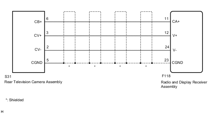
The display signal of the rear television camera assembly is transmitted to the radio and display receiver assembly.
WIRING DIAGRAM
CAUTION / NOTICE / HINT
Note
When replacing the radio and display receiver assembly, it is necessary perform the vehicle contract setting for Connected Service Click here.
PROCEDURE
-
CHECK HARNESS AND CONNECTOR (RADIO AND DISPLAY RECEIVER ASSEMBLY - REAR TELEVISION CAMERA ASSEMBLY)
-
Disconnect the F118 radio and display receiver assembly connector.
-
Disconnect the S31 rear television camera assembly connector.
-
Measure the resistance according to the value(s) in the table below.
Standard Resistance Tester Connection Condition Specified Condition F118-12 (V+) - S31-3 (CV+) Always Below 1 Ω F118-24 (V-) - S31-2 (CV-) Always Below 1 Ω F118-11 (CA+) - S31-6 (CB+) Always Below 1 Ω F118-23 (CGND) - S31-5 (CGND) Always Below 1 Ω F118-12 (V+) or S31-3 (CV+) - Body ground Always 10 kΩ or higher F118-24 (V-) or S31-2 (CV-) - Body ground Always 10 kΩ or higher F118-11 (CA+) or S31-6 (CB+) - Body ground Always 10 kΩ or higher F118-23 (CGND) or S31-5 (CGND) - Body ground Always 10 kΩ or higher
NG 
REPAIR OR REPLACE HARNESS OR CONNECTOR
OK 
-
-
CHECK RADIO AND DISPLAY RECEIVER ASSEMBLY (CA+, CGND)
-
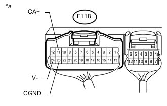
Text in Illustration *a Component with harness connected
(Radio and Display Receiver Assembly)
Remove the radio and display receiver assembly with the connector connected Click here.
-
Measure the resistance according to the value(s) in the table below.
Standard Resistance Tester Connection Condition Specified Condition F118-23 (CGND) - Body ground Always Below 1 Ω F118-24 (V-) - Body ground Always Below 1 Ω -
Measure the voltage according to the value(s) in the table below.
Standard Voltage Tester Connection Switch Condition Specified Condition F118-11 (CA+) - Body ground Engine switch on (ACC) 5.5 to 7.05 V
NG
REPLACE RADIO AND DISPLAY RECEIVER ASSEMBLY Click here
OK
-
-
CHECK REAR TELEVISION CAMERA ASSEMBLY (CV+, CGND)
-
Remove the radio and display receiver assembly with the connector connected Click here.
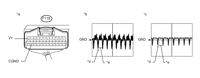
Text in Illustration *a Component with harness connected
(Radio and Display Receiver Assembly)
*b Waveform 1 *c Waveform 2 *d Synchronization Signal *e Video Waveform - - -
Check the waveform of the rear television camera assembly using an oscilloscope.
Tech Tips
-
A waterproof connector is used for the rear television camera assembly. Therefore, inspect the waveform at the radio and display receiver assembly with the connector connected.
-
The video waveform changes according to the image sent by the rear television camera assembly.
Measurement Condition Item Content Tester No. (Symbol) F118-12 (V+) - F118-23 (CGND) Tool Setting 0.2 V/DIV., 50 μS/DIV Condition Waveform 1: Engine switch on (IG), shift lever in R, camera lens is not covered, displaying an image
Waveform 2: Engine switch on (IG), shift lever in R, camera lens is covered, blacking out the screen
OK Waveform is as shown in the illustration. -
NG
REPLACE REAR TELEVISION CAMERA ASSEMBLY Click here
OK
-
-
CHECK RADIO AND DISPLAY RECEIVER ASSEMBLY
-
Replace the radio and display receiver assembly with a new or normally functioning one Click here.
-
Check the operation of rear view monitor system.
OK Rear view monitor system is operated normally.
OK
END (RADIO AND DISPLAY RECEIVER ASSEMBLY IS DEFECTIVE)
NG
REPLACE REAR TELEVISION CAMERA ASSEMBLY Click here
-