PROCEDURE
- Click here
REMOVE FUEL TANK SUB-ASSEMBLY
- Click here
REMOVE FUEL SUCTION WITH PUMP AND GAUGE TUBE ASSEMBLY
Note:Protect the connector and tube joint of the fuel suction with pump and gauge tube assembly with vinyl tape to prevent foreign matter from entering. Then clean off any mud or other foreign matter before proceeding with work.
-
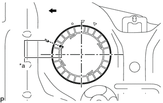
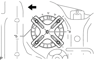
*a Co-rotation Prevention Check Mark 
Front Side of Vehicle Apply a co-rotation prevention check mark to the fuel suction with pump and gauge tube assembly and fuel tank sub-assembly.
Note:
-
The fuel tank sub-assembly cutout is attached to the protrusion on the fuel suction with pump and gauge tube assembly.
-
If the fuel suction with pump and gauge tube assembly and fuel tank sub-assembly are not firmly attached and the fuel pump gauge retainer is rotated, the fuel suction with pump and gauge tube assembly will co-rotate and result in the fuel suction with pump and gauge tube assembly and fuel tank sub-assembly being damaged.
-
Make sure to apply a co-rotation prevention check mark to prevent the fuel suction with pump and gauge tube assembly from co-rotating.
-
-
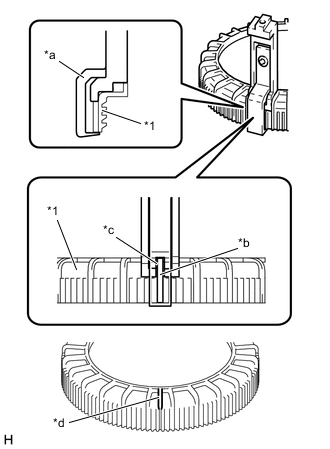
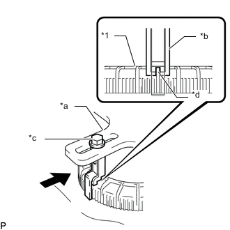
*1 Fuel Pump Gauge Retainer *a SST (claw set) *b Rib *c Cutout *d SST (Claw Set) Incorrect Installation Point (Rotational Start Point Mark of Fuel Pump Gauge Retainer) Set 4 SSTs (claw sets) to the fuel pump gauge retainer and temporarily install.
09808-14031 09808-01080 09808-01090 09808-01100 Note:
-
Align the cutout of SST (claw set) to the rib of the fuel pump gauge retainer.
-
Do not place SST on the rotational start point mark of the fuel pump gauge retainer, otherwise SST (claw set) cannot be set correctly.
-
-
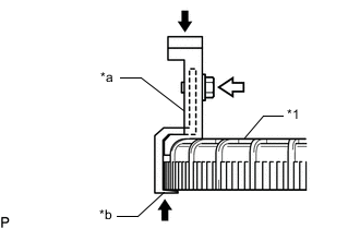
*1 Fuel Pump Gauge Retainer *a SST (Claw Set) *b Hook Press 
SST (Bolt) While firmly pressing the claw of SST into rib of the fuel pump gauge retainer, tighten the bolt.
-
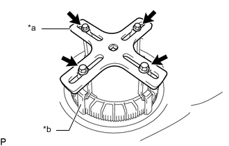
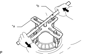
*a SST (Plate) *b SST (Claw Set) SST (Bolt) Temporarily install SST (plate) to SST (claw set) with 4 SSTs (bolts).
09808-14031 09808-01030 09808-01090 -
*a Center of Fuel Pump Gauge Retainer *b SST (Plate) Front Side of Vehicle Adjust the position of SST (plate) so that the setting hole of SST (handle) aligns with the center of the fuel pump gauge retainer.
-
*1 Fuel Pump Gauge Retainer *a SST (Plate) *b SST (Claw Set) *c SST (Bolt) *d Rib Press While firmly pressing the SST (claw set) into rib of the fuel pump gauge retainer, tighten SST (bolt).
-
*a SST (Plate) *b SST (Handle) Loosen Install SST (handle) to SST (plate).
09808-14031 09808-01010 09808-01020 -
Slowly loosen the fuel pump gauge retainer by approximately 90°.
Note:
-
Do not use any tools other than SST, such as a screwdriver, etc.
-
Do not use excessive force when pressing down on SST, as the fuel suction with pump and gauge tube assembly will place excessive force on the pump gauge retainer and be difficult to remove, and parts may be damaged.
-
Do not use an impact wrench or turn the SST handle with excessive force, as parts may be damaged.
-
-
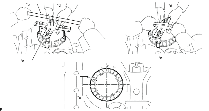
*a SST (Plate) *b SST (Handle) *c Person in Charge of Loosening *d Person in Charge of Supporting *e Co-rotation Prevention Check Mark - - While one person slowly loosens the fuel pump gauge retainer, have another person press down the rising fuel suction with pump and gauge tube assembly, securely attach the protrusion of the fuel suction with pump and gauge tube assembly to the groove of the fuel tank sub-assembly, and then remove the fuel pump gauge retainer while making sure that the fuel suction with pump and gauge tube assembly is properly aligned.
Note:
-
The fuel suction with pump and gauge tube assembly is equipped with a spring that pushes against the bottom of the fuel tank sub-assembly to constantly lift the fuel suction with pump and gauge tube assembly upwards.
-
If the fuel suction with pump and gauge tube assembly and fuel tank sub-assembly are not firmly attached and the fuel pump gauge retainer is rotated, the fuel suction with pump and gauge tube assembly will co-rotate and result in the fuel suction with pump and gauge tube assembly and fuel tank sub-assembly being damaged.
-
Do not rotate the fuel pump gauge retainer when the co-rotation prevention check mark is out of place.
-
Do not bend the arm of the fuel sender gauge assembly.
-
-
Remove the gasket from the fuel tank sub-assembly.
-