ENGINE ASSEMBLY INSTALLATION
CAUTION / NOTICE / HINT
Note
w/ DPF:
When fuel lines are disconnected, air may enter the fuel lines, leading to engine starting trouble. Therefore, perform forced regeneration and bleed the air from the fuel lines Click here.
PROCEDURE
-
INSTALL FRONT ENGINE MOUNTING INSULATOR LH
-
INSTALL FRONT ENGINE MOUNTING INSULATOR RH
-
INSTALL NO. 1 AND NO. 2 ENGINE HANGER
-
REMOVE ENGINE STAND
-
Attach an engine sling device and hang the engine with a chain block.
-
Lift the engine, and remove it from the engine stand.
Note
-
With the exception of installing the engine assembly to an engine stand or removing the engine assembly from an engine stand, do not perform any work on the engine while it is suspended, as doing so is dangerous.
-
Pay attention to the angle of the sling device as the engine assembly or engine hangers may be damaged or deformed if the angle is incorrect.
-
-
-
INSTALL DRIVE PLATE AND RING GEAR SUB-ASSEMBLY (for Automatic Transmission)
-
Using a wrench, hold the crankshaft.
-
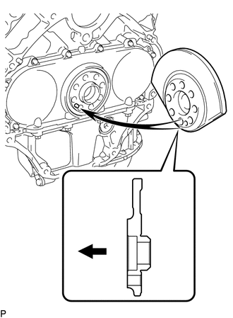
Install the rear crankshaft balancer weight.
Text in Illustration 
Engine Side Tech Tips
-
Align the pin hole of the rear crankshaft balancer weight with the pin of the crankshaft.
-
As the rear crankshaft balancer weight is not reversible, be sure to install it so that it is facing in the direction shown in the illustration.
-
-
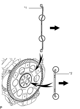
Text in Illustration *1 Drive Plate and Ring Gear *2 Rear Drive Plate Spacer Automatic Transmission Side Install the drive plate and ring gear and rear drive plate spacer with 8 new bolts.
Tech Tips
As the drive plate and ring gear and rear drive plate spacer are not reversible, be sure to install them so that they are facing in the direction shown in the illustration.
-
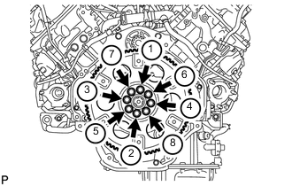
Install and uniformly tighten the 8 bolts in the sequence shown in the illustration.
- Torque:
- 182 N*m { 1856 kgf*cm, 134 ft.*lbf }
-
-
INSTALL FLYWHEEL SUB-ASSEMBLY (for Manual Transmission)
-
Temporarily install the flywheel with 8 new bolts.
Note
-
Align the crankshaft knock pin and flywheel knock pin hole.
-
Do not strike or damage the flywheel installation bolts. Be sure to handle them carefully.
-
Make sure there is no oil on the bolts.
-
-
Using a wrench, hold the crankshaft.
-
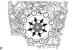
Uniformly install and tighten the 8 bolts in the sequence shown in the illustration.
- Torque:
- 182 N*m { 1856 kgf*cm, 134 ft.*lbf }
-
-
INSTALL CLUTCH DISC ASSEMBLY (for Manual Transmission)
-
INSTALL CLUTCH COVER ASSEMBLY (for Manual Transmission)
-
INSTALL ENGINE ASSEMBLY
-
Slowly lower the engine into the engine compartment.
-
Install the 4 bolts to the front mounting insulator RH and LH.
- Torque:
- 58 N*m { 591 kgf*cm, 43 ft.*lbf }
-
Remove the 4 bolts and No. 1 and No. 2 engine hangers.
-
-
INSTALL CLUTCH RELEASE CYLINDER TO FLEXIBLE HOSE TUBE (for Manual Transmission)
-
Install the clutch release cylinder to flexible hose tube with the bolt.
- Torque:
- 20 N*m { 204 kgf*cm, 15 ft.*lbf }
-
-
INSTALL MANUAL TRANSMISSION UNIT ASSEMBLY
-
INSTALL AUTOMATIC TRANSMISSION ASSEMBLY
-
INSTALL NO. 2 INTAKE MANIFOLD
-
INSTALL NO. 1 INTAKE MANIFOLD
-
INSTALL NO. 1 FUEL PIPE CLAMP (w/ DPF)
-
INSTALL FUEL HOSE BRACKET (w/ DPF)
-
INSTALL NO. 1 NOZZLE LEAKAGE PIPE (w/ DPF)
-
INSTALL NO. 2 NOZZLE LEAKAGE PIPE (w/ DPF)
-
INSTALL NO. 1 WATER BY-PASS PIPE
-
INSTALL FUEL TUBE SUB-ASSEMBLY (w/ DPF)
-
INSTALL FUEL COOLER ASSEMBLY (w/o DPF)
-
CONNECT NO. 6 WATER BY-PASS HOSE (w/o DPF)
-
INSTALL NO. 4 NOZZLE LEAKAGE PIPE (w/o DPF)
-
INSTALL NO. 3 NOZZLE LEAKAGE PIPE (w/o DPF)
-
INSTALL EGR COOLER INSULATOR (w/ EGR System)
-
INSTALL EGR VALVE ASSEMBLY WITH EGR COOLER (w/ EGR System)
-
INSTALL EGR PIPE INSULATOR (w/ EGR System)
-
INSTALL INTAKE MANIFOLD INSULATOR (w/ EGR System)
-
INSTALL NO. 3 INTAKE MANIFOLD
-
CONNECT NO. 2 ENGINE WIRE
-
INSTALL INTAKE PIPE
-
INSTALL NO. 3 NOZZLE LEAKAGE PIPE (w/ DPF)
-
INSTALL CONNECTING WIRE (w/ DPF)
-
INSTALL NO. 2 INTAKE MANIFOLD INSULATOR (w/ Intercooler)
-
INSTALL NO. 1 INTAKE MANIFOLD INSULATOR (w/ Intercooler)
-
INSTALL COMMON RAIL ASSEMBLY RH
-
INSTALL INJECTION PIPE RH
-
INSTALL NO. 1 PROTECTOR FUEL INJECTOR (w/ DPF)
-
INSTALL NO. 2 PROTECTOR FUEL INJECTOR (w/ DPF)
-
INSTALL CYLINDER HEAD COVER SILENCER RH (w/ DPF)
-
INSTALL NO. 5 INJECTION PIPE SUB-ASSEMBLY
-
CONNECT FUEL PUMP MOTOR WIRE
-
INSTALL FUEL FILTER TO INJECTION PUMP FUEL PIPE SUB-ASSEMBLY
-
INSTALL COMMON RAIL ASSEMBLY LH
-
INSTALL NO. 5 NOZZLE LEAKAGE PIPE (w/ DPF)
-
INSTALL INJECTION PIPE LH
-
INSTALL NO. 4 NOZZLE LEAKAGE PIPE (w/ DPF)
-
INSTALL CYLINDER HEAD COVER SILENCER LH (w/ DPF)
-
INSTALL NO. 1 VACUUM TRANSMITTING PIPE SUB-ASSEMBLY (w/ DPF)
-
INSTALL NO. 1 VACUUM SWITCHING VALVE ASSEMBLY (w/ DPF)
-
INSTALL NO. 2 FUEL PIPE SUB-ASSEMBLY (w/o DPF)
-
CONNECT NO. 6 INJECTION PIPE SUB-ASSEMBLY
-
CONNECT ENGINE WIRE
-
Rear Side:
-
Install the glow plug wire harness with the nut and screw grommet.
- Torque:
- 4.0 N*m { 41 kgf*cm, 35 in.*lbf }
-
w/ DPF:
Connect the 3 connectors.
-
w/o DPF:
Connect the connector.
-
Install the engine wire harness protector with the 2 bolts.
-
Install the 2 ground wires with the 2 bolts.
- Torque:
- 8.4 N*m { 86 kgf*cm, 74 in.*lbf }
-
-
LH Side:
-
Install the engine wire protector with the 2 bolts.
-
Connect the 8 connectors.
-
Attach the wire harness clamp.
-
Install the engine wire harness bracket with the bolt.
-
for RHD:
Connect the wire harness with the wire harness clamp holder.
-
Attach the 3 wire harness clamps and connect the 2 connectors.
-
w/ DPF:
Connect the 7 connectors to the injection driver.
-
w/o DPF:
Connect the 4 connectors to the injection driver.
-
Install the ground wire with the bolt.
- Torque:
- 8.4 N*m { 86 kgf*cm, 74 in.*lbf }
-
Connect the wire harness holder to the relay block.
-
Connect the 4 connectors to the relay block.
-
Connect the wire harness with the wire harness clamp holder.
-
for RHD:
Connect the wire harness with the wire harness clamp holder.
-
for RHD:
Connect the ECM connector to the ECM.
-
for RHD:
Attach the wire harness tab to the relay block.
-
Connect the 4 connectors to the relay block.
-
Connect the generator positive (+) cable to the body panel with the 2 clamps.
-
Attach the generator positive (+) cable holder to the relay block, and install the cable to the relay block with the nut.
- Torque:
- 10 N*m { 102 kgf*cm, 7 ft.*lbf }
-
Connect the wire harness with the wire harness clamp holder, and attach the ground wire clamp to the relay block side.
-
Install the ground wire to the body panel with the bolt.
- Torque:
- 8.4 N*m { 86 kgf*cm, 74 in.*lbf }
-
-
RH Side:
-
w/ Winch:
Install the ground wire with the bolt.
- Torque:
- 19 N*m { 194 kgf*cm, 14 ft.*lbf }
-
Install the engine wire harness protector with the 3 bolts.
-
Connect the 7 connectors.
-
Install the wire harness bracket with the bolt.
-
Install the glow plug wire harness with the nut and screw grommet.
- Torque:
- 4.0 N*m { 41 kgf*cm, 35 in.*lbf }
-
for RHD:
Install the wire harness holder with the bolt.
-
for RHD:
Connect the wire harness with the wire harness holder.
-
for LHD:
Connect the wire harness with the wire harness clamp holder.
-
for LHD:
Connect the ECM connector to the ECM.
-
for LHD:
Attach the wire harness tab to the relay block.
-
for LHD:
Connect the 4 connectors to the relay block.
-
-
-
INSTALL NO. 4 WATER BY-PASS PIPE
-
INSTALL NO. 3 WATER BY-PASS PIPE (w/o Viscous Heater)
-
CONNECT FUEL HOSE
-
INSTALL NO. 1 AIR CLEANER PIPE SUB-ASSEMBLY
-
INSTALL HEATER WATER PIPE SUB-ASSEMBLY (w/ Viscous Heater)
-
INSTALL NO. 2 INTAKE AIR CONNECTOR PIPE
-
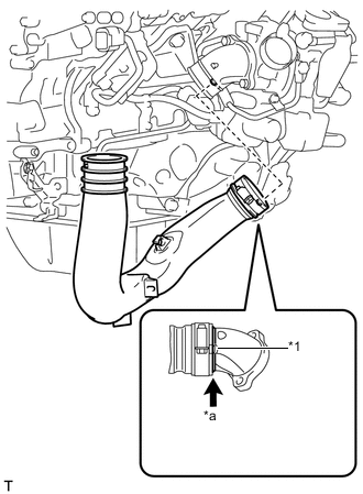
Text in Illustration *1 Hose Stopper *a No Gap Install the No. 2 intake air connector pipe to the No. 2 inlet compressor elbow.
Note
Make sure there is no gap between the air pipe and hose stopper on the elbow side.
-
Install the bolt of the No. 2 intake air connector pipe.
- Torque:
- 21 N*m { 214 kgf*cm, 15 ft.*lbf }
Note
Do not excessively pull the air pipe towards the front of the engine.
-
Tighten the hose clamp on the elbow side.
- Torque:
- 6.0 N*m { 61 kgf*cm, 53 in.*lbf }
Tech Tips
-
Align the 2 protrusions of the air pipe and elbow.
-
Install the air pipe so that the protrusion on the pipe side is within the range of the protrusion on the elbow side.
-
After tightening, a gap between the air pipe and hose stopper on the elbow side is acceptable.
-
Make sure the direction of the hose clamp is as shown in the illustration.
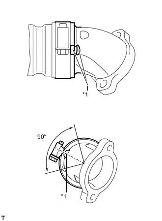
Text in Illustration *1 Protrusion -
w/ Intercooler:
Connect the vacuum hose.
-
-
ADJUST COMPRESSOR OIL
-
INSTALL COOLER COMPRESSOR ASSEMBLY
-
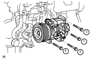
Temporarily install the cooler compressor with the 4 bolts.
-
Tighten the 4 bolts in the order shown in the illustration.
- Torque:
- 25 N*m { 250 kgf*cm, 18 ft.*lbf }
-
Attach the 3 wire harness clamps and connect the 4 connectors.
-
-
INSTALL SUCTION HOSE SUB-ASSEMBLY
-
INSTALL NO. 1 COOLER REFRIGERANT DISCHARGE HOSE
-
INSTALL NO. 2 AIR CLEANER PIPE SUB-ASSEMBLY
-
INSTALL NO. 2 AIR TUBE ASSEMBLY
-
Apply a light coat of washer fluid to a new O-ring, and install it to the No. 2 air tube.
-
Install the No. 2 air tube with the bolt.
- Torque:
- 21 N*m { 214 kgf*cm, 15 ft.*lbf }
-
-
INSTALL NO. 4 AIR TUBE
-
INSTALL NO. 2 AIR HOSE
-
INSTALL NO. 1 AIR TUBE ASSEMBLY
-
Apply a light coat of washer fluid to a new O-ring, and install it to the No. 1 air tube.
-
Install the No. 1 air tube with the bolt.
- Torque:
- 21 N*m { 214 kgf*cm, 15 ft.*lbf }
-
-
INSTALL NO. 3 AIR TUBE
-
INSTALL NO. 1 AIR HOSE
-
INSTALL DIESEL THROTTLE BODY ASSEMBLY LH
-
INSTALL NO. 3 INTERCOOLER SUPPORT BRACKET
-
INSTALL NO. 1 GAS FILTER
-
INSTALL TUBE CONNECTOR TO FLEXIBLE HOSE TUBE (for Manual Transmission)
-
INSTALL AIR TUBE SUB-ASSEMBLY LH
-
INSTALL CLUTCH HOSE (for Manual Transmission)
-
INSTALL DIESEL THROTTLE BODY ASSEMBLY RH
-
INSTALL AIR TUBE SUB-ASSEMBLY RH
-
INSTALL NO. 2 ENGINE OIL LEVEL DIPSTICK GUIDE
-
CONNECT WATER HOSE SUB-ASSEMBLY
-
INSTALL NO. 2 COOL AIR INLET (w/o Intercooler)
-
INSTALL NO. 1 COOL AIR INLET (w/o Intercooler)
-
CONNECT FUEL TUBE
-
Install new No. 1 and No. 3 fuel tube clamps.
-
w/ DPF:
Connect the 2 fuel tubes to the clamps.
-
w/o DPF:
Connect the 3 fuel tubes to the clamps.
-
-
CONNECT FRONT DIFFERENTIAL BREATHER TUBE
-
ADD ENGINE OIL
-
INSTALL RADIATOR ASSEMBLY
-
CONNECT RADIATOR SIDE DEFLECTOR LH
-
CONNECT RADIATOR SIDE DEFLECTOR RH (for Manual Transmission)
-
INSTALL TRANSMISSION OIL COOLER AIR DUCT (for Automatic Transmission)
-
INSTALL FRONT BUMPER COVER
-
INSTALL RADIATOR GRILLE
-
INSTALL FRONT BUMPER WINCH COVER (w/ Winch)
-
INSTALL FAN PULLEY
-
INSTALL FAN SHROUD WITH FAN
-
INSTALL OIL COOLER TUBE (for Automatic Transmission)
-
INSTALL V-RIBBED BELT
-
INSTALL NO. 3 IDLER PULLEY (w/ Viscous Heater)
-
INSTALL NO. 1 IDLER PULLEY (w/ Viscous Heater)
-
INSTALL V-RIBBED BELT (w/ Viscous Heater)
-
CONNECT NO. 2 RADIATOR HOSE
-
CONNECT NO. 1 RADIATOR HOSE
-
INSTALL VANE PUMP ASSEMBLY
-
w/ DPF: Click here
-
w/o DPF: Click here
-
-
INSTALL RADIATOR RESERVOIR ASSEMBLY
-
INSTALL NO. 1 OIL RESERVOIR BRACKET
-
INSTALL VANE PUMP OIL RESERVOIR ASSEMBLY
-
INSTALL AIR CLEANER CASE
-
Install the air cleaner case with the 3 bolts.
- Torque:
- 5.0 N*m { 51 kgf*cm, 44 in.*lbf }
-
Attach the wire harness clamp to the air cleaner case.
-
-
INSTALL AIR CLEANER FILTER ELEMENT
-
INSTALL INTAKE AIR CONNECTOR
-
TEMPORARILY INSTALL NO. 1 AIR CLEANER HOSE
-
INSTALL AIR CLEANER CAP SUB-ASSEMBLY
-
INSTALL INTERCOOLER ASSEMBLY (w/ Intercooler)
-
INSTALL SUB-BATTERY
-
INSTALL MAIN BATTERY
-
INSTALL NO. 3 ENGINE ROOM WIRE
-
INSTALL FRONT WHEEL
-
BLEED CLUTCH LINE
-
CHECK FOR CLUTCH FLUID LEAK
-
CONNECT CABLE TO NEGATIVE BATTERY TERMINAL
Note
When disconnecting the cable, some systems need to be initialized after the cable is reconnected Click here.
-
Connect the cables to the negative (-) main battery and sub-battery terminals.
-
-
BLEED AIR FROM FUEL SYSTEM
-
ADD ENGINE COOLANT
-
INSPECT FOR FUEL LEAK
-
INSPECT FOR OIL LEAK
-
INSPECT FOR COOLANT LEAK
-
INSPECT FOR EXHAUST GAS LEAK
-
CHARGE REFRIGERANT
-
WARM UP ENGINE
-
CHECK FOR REFRIGERANT GAS LEAK
-
INSTALL FRONT FENDER APRON SEAL REAR LH
-
Install the front fender apron seal rear LH with the 4 clips.
-
-
INSTALL FRONT FENDER APRON SEAL FRONT LH
-
w/o KDSS:
Install the front fender apron seal front LH with the 4 clips.
-
w/ KDSS:
Install the front fender apron seal front LH with the 3 clips.
-
-
INSTALL FRONT FENDER APRON SEAL REAR RH
-
Install the front fender apron seal rear RH with the 4 clips.
-
-
INSTALL FRONT FENDER APRON SEAL FRONT RH
-
Install the front fender apron seal front RH with the 3 clips.
-
-
INSTALL OIL PAN PROTECTOR ASSEMBLY
-
INSTALL NO. 2 ENGINE UNDER COVER
-
Install the No. 2 engine under cover with the 2 bolts.
- Torque:
- 29 N*m { 296 kgf*cm, 21 ft.*lbf }
-
-
INSTALL NO. 1 ENGINE UNDER COVER SUB-ASSEMBLY
-
Install the No. 1 engine under cover with the 10 bolts.
- Torque:
- 29 N*m { 296 kgf*cm, 21 ft.*lbf }
-
-
INSTALL FRONT FENDER SPLASH SHIELD SUB-ASSEMBLY RH
-
Install the front fender splash shield RH with the clip, and then install the 3 bolts and 2 screws.
-
-
INSTALL FRONT FENDER SPLASH SHIELD SUB-ASSEMBLY LH
-
Install the front fender splash shield LH with the clip, and then install the 3 bolts and screw.
-
-
INSTALL COWL TOP VENTILATOR LOUVER SUB-ASSEMBLY
-
INSTALL HOOD SUB-ASSEMBLY
-
Install the hood with the 4 bolts.
- Torque:
- 13 N*m { 133 kgf*cm, 10 ft.*lbf }
-
Install the 2 hood supports with the 2 bolts.
- Torque:
- 18 N*m { 184 kgf*cm, 13 ft.*lbf }
Note
-
As much as possible avoid touching the stroke portions of the rod to prevent foreign matter from attaching to it. Be sure to hold the cylinders while servicing.
-
Do not wear cotton gloves or other similar materials when handling the rod. Fibers may attach to the rod and result in gas leaks.
-
Do not apply any load to the cylinders in the horizontal direction in order to prevent the rod from being deformed.
-
Install the hood support while supporting the hood by hand.
-
-
ADJUST HOOD SUB-ASSEMBLY
-
INSPECT ENGINE OIL LEVEL
-
INSPECT ENGINE COOLANT LEVEL IN RESERVOIR
-
INSPECT ENGINE IDLE SPEED
-
INSPECT MAXIMUM ENGINE SPEED
-
INSTALL UPPER RADIATOR SUPPORT SEAL
-
INSTALL NO. 1 ENGINE COVER SUB-ASSEMBLY (w/ Intercooler)
-
PERFORM CRANK TIME COMPENSATION RESET FUNCTION