CYLINDER HEAD GASKET(w/o DPF) REMOVAL

CAUTION / NOTICE / HINT
CAUTION:
When replacing an injector (including interchanging injectors between cylinders), common rail, cylinder head, or intake manifold, replace the corresponding injection pipes with a new one.
PROCEDURE
-
PRECAUTION
Note
After turning the ignition switch off, waiting time may be required before disconnecting the cable from the battery terminal. Therefore, make sure to read the disconnecting the cable from the battery terminal notice before proceeding with work Click here.
-
DISCONNECT CABLE FROM NEGATIVE BATTERY TERMINAL
Note
When disconnecting the cable some systems need to be initialized after the cable is reconnected Click here.
-
REMOVE ENGINE ASSEMBLY
-
Remove the engine assembly from the vehicle Click here.
-
-
CHECK INJECTOR COMPENSATION CODE
-
REMOVE NO. 1 INTAKE AIR CONNECTOR PIPE
-
REMOVE GENERATOR ASSEMBLY
-
REMOVE NO. 1 ENGINE OIL LEVEL DIPSTICK GUIDE
-
DISCONNECT NO. 2 VENTILATION HOSE
-
DISCONNECT NO. 2 TURBO WATER HOSE
-
DISCONNECT BREATHER PLUG RH
-
REMOVE NO. 1 EXHAUST MANIFOLD HEAT INSULATOR
-
DISCONNECT NO. 1 OUTLET TURBO OIL HOSE
-
REMOVE NO. 1 TURBO WATER PIPE SUB-ASSEMBLY
-
REMOVE NO. 1 TURBOCHARGER STAY
-
REMOVE NO. 1 VENTILATION TUBE SUB-ASSEMBLY
-
REMOVE NO. 1 TURBOCHARGER SUB-ASSEMBLY WITH EXHAUST MANIFOLD RH
-
DISCONNECT NO. 3 VENTILATION HOSE
-
DISCONNECT BREATHER PLUG LH
-
DISCONNECT NO. 2 TURBO WATER HOSE
-
REMOVE NO. 2 EXHAUST MANIFOLD HEAT INSULATOR
-
REMOVE NO. 3 TURBO WATER PIPE SUB-ASSEMBLY
-
REMOVE FRONT WATER BY-PASS JOINT
-
REMOVE NO. 2 TURBO WATER PIPE SUB-ASSEMBLY
-
DISCONNECT NO. 2 OUTLET TURBO OIL HOSE
-
REMOVE NO. 2 TURBOCHARGER STAY
-
REMOVE NO. 2 VENTILATION TUBE SUB-ASSEMBLY
-
REMOVE NO. 2 TURBOCHARGER SUB-ASSEMBLY WITH EXHAUST MANIFOLD LH
-
REMOVE NO. 1 INTAKE AIR CONNECTOR BRACKET
-
REMOVE AIR TUBE SUPPORT
-
REMOVE NO. 1 WATER BY-PASS PIPE SUB-ASSEMBLY
-
REMOVE NO. 4 VACUUM TRANSMITTING PIPE SUB-ASSEMBLY (w/ Intercooler)
-
REMOVE ENGINE MOUNTING BRACKET RH
-
REMOVE NO. 1 CYLINDER BLOCK INSULATOR
-
REMOVE NO. 2 INTAKE AIR CONNECTOR BRACKET
-
REMOVE TURBOCHARGER WIRE
-
REMOVE NO. 3 VACUUM TRANSMITTING PIPE SUB-ASSEMBLY
-
REMOVE NO. 2 WATER BY-PASS PIPE SUB-ASSEMBLY
-
REMOVE ENGINE MOUNTING BRACKET LH
-
REMOVE NO. 2 CYLINDER BLOCK INSULATOR
-
REMOVE COMPRESSOR BRACKET
-
REMOVE STIFFENER INSULATOR RH (w/ Intercooler)
-
DISCONNECT NO. 1 OIL COOLER HOSE
-
DISCONNECT NO. 2 OIL COOLER HOSE
-
REMOVE CRANKSHAFT PULLEY
-
REMOVE TIMING GEAR COVER SPACER (w/ Intercooler)
-
REMOVE OIL FILTER ELEMENT
-
REMOVE OIL FILTER BRACKET SUB-ASSEMBLY
-
REMOVE ENGINE OIL LEVEL SENSOR
-
REMOVE NO. 2 OIL PAN SUB-ASSEMBLY
-
REMOVE OIL STRAINER SUB-ASSEMBLY
-
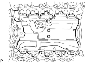
REMOVE NO. 1 OIL PAN SUB-ASSEMBLY
-
REMOVE CAMSHAFT POSITION SENSOR
-
REMOVE CRANKSHAFT POSITION SENSOR
-
REMOVE VISCOUS HEATER ASSEMBLY WITH MAGNET CLUTCH (w/ Viscous Heater)
-
REMOVE NO. 1 IDLER PULLEY BRACKET (w/ Viscous Heater)
-
REMOVE WATER INLET
-
REMOVE THERMOSTAT
-
REMOVE TIMING GEAR COVER INSULATOR (w/ Intercooler)
-
REMOVE FAN BRACKET SUB-ASSEMBLY
-
REMOVE NO. 2 IDLER PULLEY (w/ Viscous Heater)
-
REMOVE NO. 2 IDLER PULLEY BRACKET (w/ Viscous Heater)
-
REMOVE V-RIBBED BELT TENSIONER ASSEMBLY
-
DISCONNECT INLET WATER HOSE
-
REMOVE STARTER ASSEMBLY
-
REMOVE STARTER HOSE BRACKET
-

Remove the 2 bolts and starter hose bracket.
-
-
REMOVE CLUTCH FLEXIBLE HOSE BRACKET (for Manual Transmission)
-

Remove the 2 bolts and clutch flexible hose bracket.
-
-
REMOVE NO. 2 INTERCOOLER SUPPORT BRACKET
-
REMOVE WATER OUTLET
-
REMOVE WATER OUTLET PIPE
-
REMOVE NO. 1 GLOW PLUG CONNECTOR
-
REMOVE GLOW PLUG ASSEMBLY
-
REMOVE NO. 1 VACUUM SWITCHING VALVE ASSEMBLY (w/ Intercooler)
-
REMOVE NO. 1 VACUUM TRANSMITTING PIPE SUB-ASSEMBLY
-
REMOVE CYLINDER HEAD COVER SILENCER RH (w/ Intercooler)
-
REMOVE CYLINDER HEAD COVER SILENCER LH (w/ Intercooler)
-
REMOVE VACUUM PUMP ASSEMBLY (w/ Intercooler)
-
REMOVE NOZZLE HOLDER SEAL RH
-
REMOVE CYLINDER HEAD COVER SUB-ASSEMBLY RH
-
REMOVE NOZZLE HOLDER GASKET RH
-
REMOVE OIL SEPARATOR ASSEMBLY
-
REMOVE NOZZLE HOLDER SEAL LH
-
REMOVE CYLINDER HEAD COVER SUB-ASSEMBLY LH
-
REMOVE NOZZLE HOLDER GASKET LH
-
REMOVE FUEL INJECTOR RH
-
REMOVE FUEL INJECTOR LH
-
REMOVE WATER PUMP ASSEMBLY
-
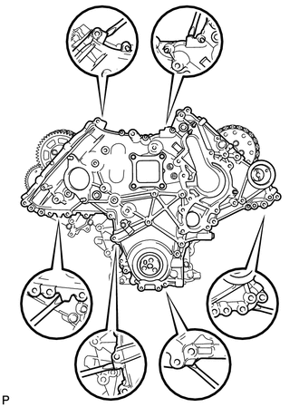
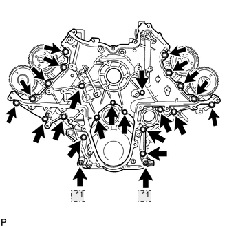
REMOVE TIMING CHAIN COVER SUB-ASSEMBLY
-
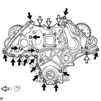
*1 Nut Remove the 4 nuts and 16 bolts.
-
Using a screwdriver, remove the timing chain cover by prying between the timing chain cover and cylinder head or cylinder block.
Tech Tips
Tape the screwdriver tip before use.
-
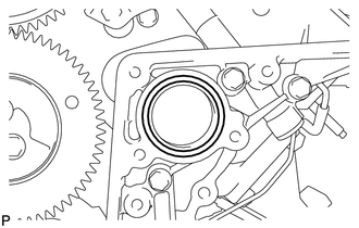
Remove the O-ring from the timing gear case.
-
-
REMOVE FRONT CRANKSHAFT OIL SEAL
-
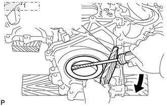
*1 Wooden Block Place the timing chain cover on wooden blocks.
-
Using a screwdriver and wooden block, pry out the oil seal.
Note
Do not damage the surface of the oil seal press fit hole.
Tech Tips
Tape the screwdriver tip before use.
-
-
SET NO. 1 CYLINDER TO TDC/COMPRESSION
-
Temporarily install the 2 crankshaft pulley set bolts to the crankshaft.
-
Turn the crankshaft clockwise to set the No. 1 cylinder to TDC.
-
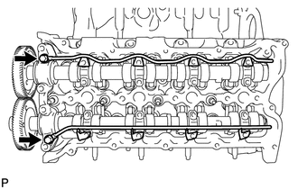
With the crankshaft key 45° counterclockwise from the top position, check that the timing marks of the RH and LH camshaft timing gears are aligned. If not as specified, turn the crankshaft 1 revolution (360°) and align the timing marks as shown below.

*1 Top *2 Key -
Remove the 2 crankshaft pulley set bolts.
-
-
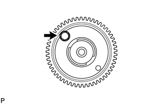
REMOVE NO. 1 CRANKSHAFT POSITION SENSOR PLATE
-
Using a T30 "TORX" wrench, remove the 2 screws and crankshaft position sensor plate.
-
-
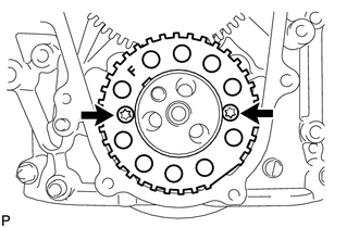
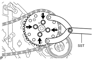
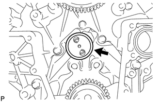
REMOVE PUMP DRIVE SHAFT GEAR
-
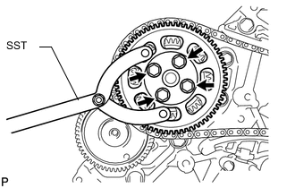
Using SST, hold the pump drive shaft gear.
- SST
- 09960-10010 ( 09962-01000, 09963-01000 )
-
Remove the 4 bolts and pump drive shaft gear.
-
-
REMOVE NO. 1 CHAIN TENSIONER ASSEMBLY
-
Push the tensioner slipper away from the tensioner, and move the stopper plate clockwise to release the lock as shown in A.
-
Push down the tensioner slipper and move the stopper plate counterclockwise to set the lock as shown in B.
-
Push the tensioner slipper away from the tensioner, and insert a hexagon wrench into the stopper plate hole as shown in C.
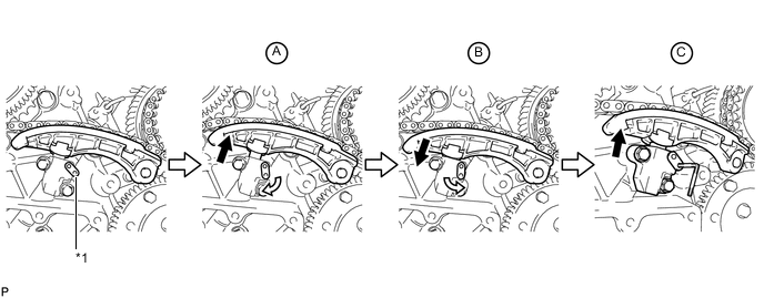
*1 Stopper Plate -
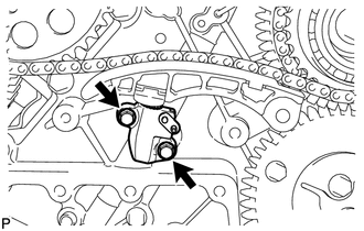
Remove the 2 bolts and No. 1 chain tensioner.
-
-
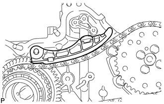
REMOVE NO. 1 CHAIN TENSIONER SLIPPER
-
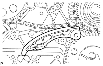
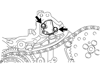
REMOVE NO. 1 CHAIN VIBRATION DAMPER
-
Remove the 2 bolts and No. 1 chain vibration damper.
-
-
REMOVE NO. 1 CAMSHAFT TIMING SPROCKET AND NO. 1 TIMING CHAIN
-
REMOVE NO. 2 CHAIN TENSIONER ASSEMBLY
-
Push the tensioner slipper away from the tensioner, and move the stopper plate clockwise to release the lock as shown in A.
-
Push up the tensioner slipper and move the stopper plate counterclockwise to set the lock as shown in B.
-
Push the tensioner slipper away from the tensioner, and insert a hexagon wrench into the stopper plate hole as shown in C.
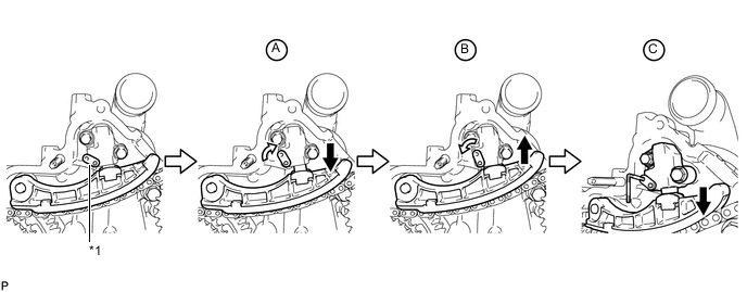
*1 Stopper Plate -
Remove the 2 bolts and No. 2 chain tensioner.
-
-
REMOVE NO. 2 CHAIN TENSIONER SLIPPER
-
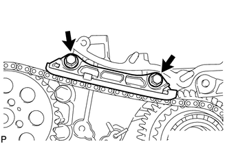
REMOVE NO. 2 CHAIN VIBRATION DAMPER
-
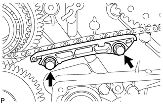
Remove the 2 bolts and No. 2 chain vibration damper.
-
-
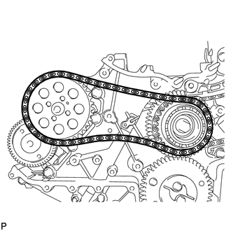
REMOVE NO. 2 CAMSHAFT TIMING SPROCKET AND NO. 2 TIMING CHAIN
-
Using SST, hold the No. 2 camshaft timing sprocket.
- SST
- 09960-10010 ( 09962-01000, 09963-01000 )
-
Remove the 4 bolts, No. 2 camshaft timing sprocket and No. 2 timing chain.
-
-
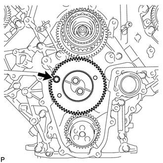
REMOVE FUEL SUPPLY PUMP DRIVE GEAR NUT
-
Using SST, hold the idle gear.
- SST
- 09960-10010 ( 09962-01000, 09963-00700 )
-
Remove the nut.

*1 w/ Intercooler: *2 w/o Intercooler:
-
-
REMOVE IDLE GEAR ASSEMBLY
-
w/ Intercooler:
Using a 8 mm x 1.25 pitch service bolt with a length of 15 mm or more, fix the idle gear in place.
- Torque:
- 13 N*m { 133 kgf*cm, 10 ft.*lbf }
-

*1 w/ Intercooler: *2 w/o Intercooler: Remove the 2 bolts, idle gear thrust plate and idle gear.
-
-
REMOVE NO. 1 IDLE GEAR SHAFT
-
REMOVE FUEL SUPPLY PUMP DRIVE GEAR
-

Using SST, remove the fuel supply pump drive gear.
- SST
- 09950-50013 ( 09951-05010, 09952-05010, 09953-05020, 09954-05031 )
-
-
REMOVE FUEL PUMP MOTOR WIRE
-
REMOVE FUEL SUPPLY PUMP ASSEMBLY
-
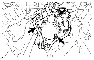
Using a 6 mm hexagon wrench, remove the hexagon bolt. Then remove the 2 nuts and fuel supply pump.
-
Remove the O-ring.
-
-
REMOVE V-BANK SILENCER
-
REMOVE TIMING GEAR CASE SUB-ASSEMBLY
-
*1 Nut Remove the 22 bolts, 2 nuts and timing gear case shown in the illustration.
-
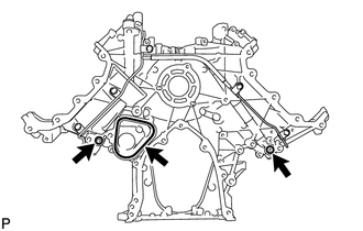
Remove the 2 O-rings and timing gear case gasket.
-
-
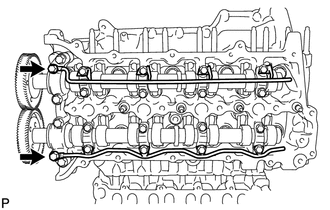
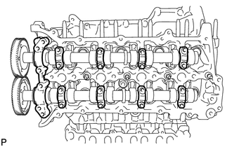
REMOVE NO. 1 AND NO. 2 CAMSHAFTS
-
Using a 6 mm x 1.0 pitch service bolt with a length of 16 mm or more, fix the No. 1 camshaft in place.
- Torque:
- 8.0 N*m { 82 kgf*cm, 71 in.*lbf }
-
Loosen the 2 union bolts.
-
Uniformly loosen and remove the 20 bolts in the sequence shown in the illustration.
-
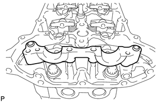
Remove the 2 union bolts and No. 1 and No. 2 oil feed pipes.
-
Remove the 8 No. 3 camshaft bearing caps and No. 1 camshaft bearing cap.
Tech Tips
Be sure to arrange the removed parts for each installation position separately.
-

Remove the No. 1 and No. 2 camshafts.
-
-
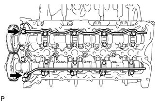
REMOVE NO. 3 AND NO. 4 CAMSHAFTS
-
Using an 6 mm x 1.0 pitch service bolt with a length of 16 mm or more, fix the No. 4 camshaft in place.
- Torque:
- 8.0 N*m { 82 kgf*cm, 71 in.*lbf }
-
Loosen the 2 union bolts.
-
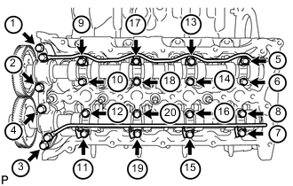
Uniformly loosen and remove the 20 bolts in the sequence shown in the illustration.
-
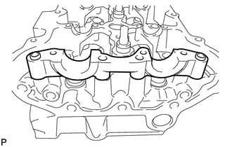
Remove the 2 union bolts, and No. 3 and No. 4 oil feed pipes.
-
Remove the 8 No. 3 camshaft bearing caps and No. 4 camshaft bearing cap.
Tech Tips
Be sure to arrange the removed parts for each installation position separately.
-
Remove the No. 3 and No. 4 camshafts.
-
-
REMOVE NO. 2 CAMSHAFT BEARING CAP
-
REMOVE NO. 5 CAMSHAFT BEARING CAP
-
REMOVE NO. 1 VALVE ROCKER ARM
-
Remove the 16 No. 1 valve rocker arms.
Tech Tips
Be sure to arrange the removed parts for each installation position separately.
-
-
REMOVE NO. 2 VALVE ROCKER ARM
-
Remove the 16 No. 2 valve rocker arms.
Tech Tips
Be sure to arrange the removed parts for each installation position separately.
-
-
REMOVE NO. 1 VALVE LASH ADJUSTER ASSEMBLY
-
Remove the 16 No. 1 valve lash adjusters.
Tech Tips
Be sure to arrange the removed parts for each installation position separately.
-
-
REMOVE NO. 2 VALVE LASH ADJUSTER ASSEMBLY
-
Remove the 16 No. 2 valve lash adjusters.
Tech Tips
Be sure to arrange the removed parts for each installation position separately.
-
-
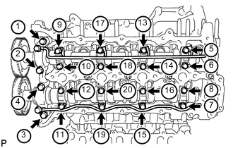
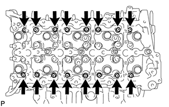
REMOVE CYLINDER HEAD SUB-ASSEMBLY RH
-
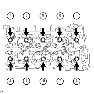
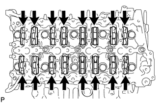
Uniformly loosen and remove the 10 bolts and 10 spacers in the sequence shown in the illustration. Then remove the cylinder head.
Note
-
Be careful not to drop washers into the cylinder head.
-
Head warpage or cracking could result from removing bolts in an incorrect order.
Tech Tips
Be sure to arrange the removed parts for each installation position separately.
-
-
-
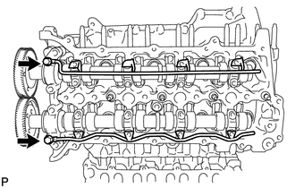
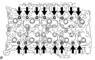
REMOVE CYLINDER HEAD SUB-ASSEMBLY LH
-
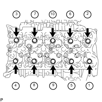
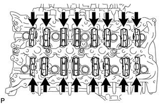
Uniformly loosen and remove the 10 bolts and 10 spacers in the sequence shown in the illustration. Then remove the cylinder head.
Note
-
Be careful not to drop washers into the cylinder head.
-
Head warpage or cracking could result from removing bolts in an incorrect order.
Tech Tips
Be sure to arrange the removed parts for each installation position separately.
-
-
-
REMOVE NO. 1 CYLINDER HEAD GASKET
-
REMOVE NO. 2 CYLINDER HEAD GASKET