CAMSHAFT(w/o DPF) INSTALLATION

CAUTION / NOTICE / HINT
CAUTION:
When replacing an injector (including interchanging injectors between cylinders), common rail, cylinder head, or intake manifold, replace the corresponding injection pipes with a new one.
PROCEDURE
-
CHECK INJECTOR COMPENSATION CODE
-
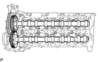
INSTALL NO. 3 AND NO. 4 CAMSHAFTS
Note
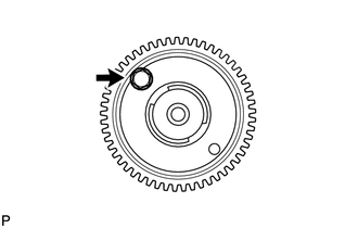
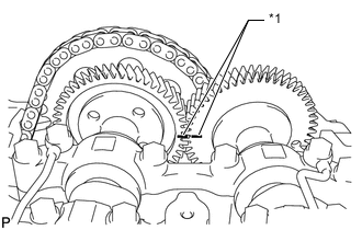
If replacing a camshaft with a new one, make a matchmark on the new camshaft in the same place as the old camshaft. Determine the matchmark placement by using the dot mark as a reference point and counting the number of gear teeth from the dot mark to the matchmark as shown in the illustration.
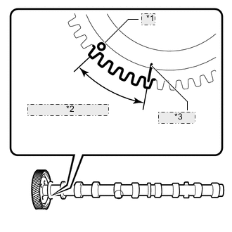
*1 Dot Mark *2 Number of Gear Teeth *3 Matchmark
-
w/o Intercooler:
When replacing the No. 4 camshaft with a new one, install a new hole plug Click here.
-
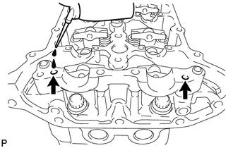
Add more than 19 cc (1.16 cu. in.) of engine oil into the cylinder head side oil holes.
-
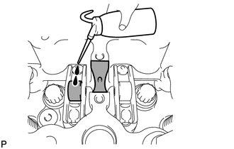
Apply engine oil to the rollers of the valve rocker arms and the camshaft housing of the cylinder head.
-
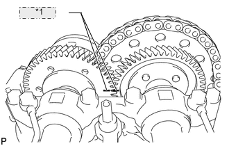
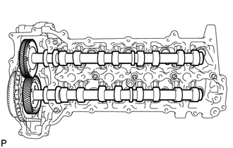
*1 Matchmark Install the No. 3 and No. 4 camshafts.
-
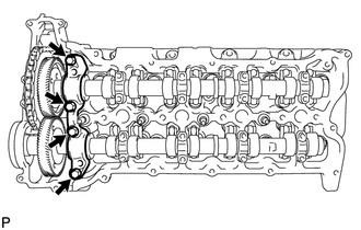
Apply engine oil to the camshaft journals, lobes, thrust portion and gears.
-
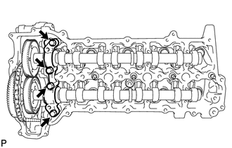
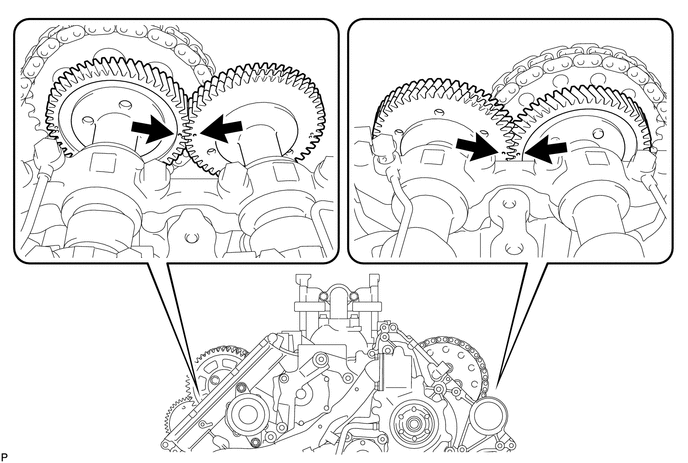
Align the matchmarks of the No. 3 and No. 4 camshaft timing gears as shown in the illustration.
-
-
Place the camshafts into the cylinder head.
Note
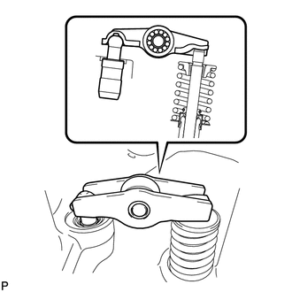
Before and after setting the camshafts, firmly set the rocker arms to the lash adjusters.
-
Install the No. 4 camshaft bearing cap.
-
Align the No. 4 camshaft bearing cap and the ring pins of the No. 5 camshaft bearing cap.
-
Temporarily install the 4 bolts by hand.
-
-
Install the No. 3 camshaft bearing caps.
-
Confirm the marks and numbers on the camshaft bearing caps and place them in their proper position and direction.
-
Temporarily install the 8 bolts, which are not installed with the oil feed pipe, by hand.
-
-
Temporarily install the No. 3 and No. 4 camshaft oil feed pipes with the 8 bolts by hand.
Note
If even one of the pipe bolt holes does not match its camshaft bearing cap bolt hole, replace the camshaft oil feed pipe.
Tech Tips
The pipe is bent on the intake side, and straight on the exhaust side.
-

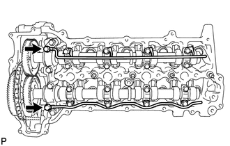
Temporarily install the 2 union bolts by hand.
-

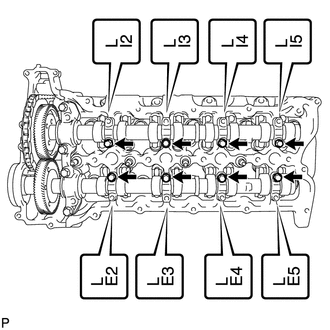
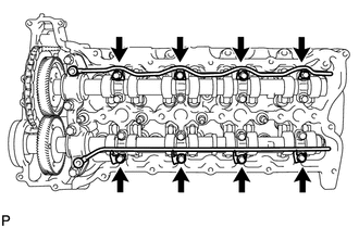
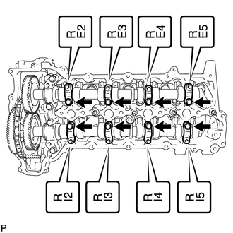
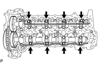
*a 12 mm Head Bolt *b 10 mm Head Bolt Uniformly tighten the 20 bolts in several steps in the order shown in the illustration.
- Torque:
- for 12 mm head bolt of No. 4 camshaft bearing cap
- 21 N*m { 214 kgf*cm, 15 ft.*lbf }
- for 10 mm head bolt of No. 3 camshaft bearing cap
- 10 N*m { 102 kgf*cm, 7 ft.*lbf }
-
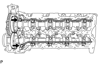
Tighten the 2 union bolts.
- Torque:
- 17 N*m { 173 kgf*cm, 13 ft.*lbf }
-
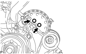
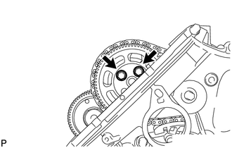
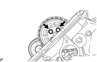
Remove the service bolt from the No. 4 camshaft timing gear.
Note
Do not drop the bolt into the engine.
Tech Tips
If the bolt is difficult to remove, rotate the camshaft and remove the bolt. Then realign the matchmarks of the No. 3 and No. 4 camshaft timing gears.
-
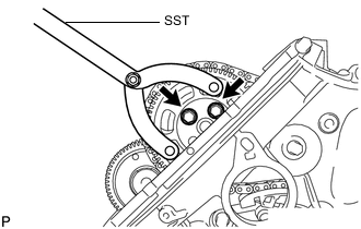
Temporarily install the No. 2 timing chain and No. 2 camshaft timing sprocket to the No. 3 camshaft with the 2 bolts.
-
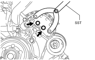
Using SST, hold the No. 2 camshaft timing sprocket. Tighten the 2 bolts.
- SST
- 09960-10010 ( 09962-01000, 09963-01000 )
- Torque:
- 25 N*m { 250 kgf*cm, 18 ft.*lbf }
-
Rotate the crankshaft pulley clockwise so that the 2 remaining pump drive shaft gear bolts can be installed.
-
Temporarily install the 2 bolts to the No. 3 camshaft.
-
Using SST, hold the No. 2 camshaft timing sprocket. Tighten the 2 bolts.
- SST
- 09960-10010 ( 09962-01000, 09963-01000 )
- Torque:
- 25 N*m { 250 kgf*cm, 18 ft.*lbf }
-
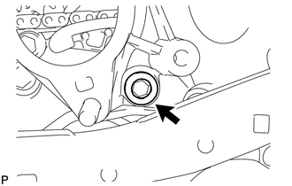
Remove the hexagon wrench from the No. 2 chain tensioner.
-
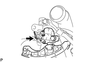
Remove the adhesive from the threads of the taper screw plug and the bolt hole of the timing gear case.
-
Apply adhesive to 3 or more threads of the taper screw plug.
Adhesive Toyota Genuine Adhesive 1344, Three Bond 1344 or equivalent -
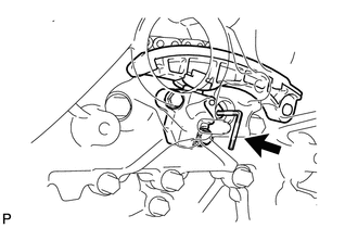
Using a 10 mm hexagon wrench, install the taper screw plug.
- Torque:
- 15 N*m { 153 kgf*cm, 11 ft.*lbf }
-
-
INSTALL NO. 1 AND NO. 2 CAMSHAFTS
*1 Dot Mark *2 Number of Gear Teeth *3 Matchmark Note
If replacing a camshaft with a new one, make a matchmark on the new camshaft in the same place as the old camshaft. Determine the matchmark placement by using the dot mark as a reference point and counting the number of gear teeth from the dot mark to the matchmark as shown in the illustration.
-
Add more than 19 cc (1.16 cu. in.) of engine oil into the cylinder head side oil holes.
-
Apply engine oil to the rollers of the valve rocker arms and the camshaft housing of the cylinder head.
-
Install the No. 1 and No. 2 camshafts.
-
Apply engine oil to the camshaft journals, lobes, thrust portion and gears.
-
*1 Matchmark Align the matchmarks of the No. 1 and No. 2 camshaft timing gears as shown in the illustration.
-
Place the 2 camshafts into the cylinder head.
Note
Before and after setting the camshafts, firmly set the rocker arms to the lash adjusters.
-
-
Install the No. 1 camshaft bearing cap.
-
Align the No. 1 camshaft bearing cap and the ring pins of the No. 2 camshaft bearing cap.
-
Temporarily install the 4 bolts by hand.
-
-
Install the No. 3 camshaft bearing caps.
-
Confirm the marks and numbers on the camshaft bearing caps and place them in their proper position and direction.
-
Temporarily install the 8 bolts, which are not installed with the oil feed pipe, by hand.
-
-
Temporarily install the No. 1 and No. 2 camshaft oil feed pipes with the 8 bolts by hand.
Note
If even one of the pipe bolt holes does not match its camshaft bearing cap bolt hole, replace the camshaft oil feed pipe.
Tech Tips
The pipe is bent on the intake side, and straight on the exhaust side.
-
Temporarily install the 2 union bolts by hand.
-

*a 12 mm Head Bolt *b 10 mm Head Bolt Uniformly tighten the 20 bolts in several steps in the order shown in the illustration.
- Torque:
- for 12 mm head bolt of No. 1 camshaft bearing cap
- 21 N*m { 214 kgf*cm, 15 ft.*lbf }
- for 10 mm head bolt of No. 3 camshaft bearing cap
- 10 N*m { 102 kgf*cm, 7 ft.*lbf }
-
Tighten the 2 union bolts.
- Torque:
- 17 N*m { 173 kgf*cm, 13 ft.*lbf }
-
Remove the service bolt from the No. 1 camshaft timing gear.
Note
Do not drop the bolt into the engine.
Tech Tips
If the bolt is difficult to remove, rotate the camshaft and remove the bolt. Then realign the matchmarks of the No. 1 and No. 2 camshaft timing gears.
-
Temporarily install the No. 1 timing chain and No. 1 camshaft timing sprocket to the No. 2 camshaft.
-
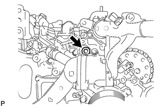
Temporarily install the pump drive shaft gear with the 2 bolts.
-
Using SST, hold the pump drive shaft gear. Tighten the 2 bolts.
- SST
- 09960-10010 ( 09962-01000, 09963-01000 )
- Torque:
- 25 N*m { 250 kgf*cm, 18 ft.*lbf }
-
Rotate the crankshaft clockwise so that the 2 remaining pump drive shaft gear bolts can be installed.
-
Temporarily install the 2 bolts to the pump drive shaft gear.
-
Using SST, hold the pump drive shaft gear. Tighten the 2 bolts.
- SST
- 09960-10010 ( 09962-01000, 09963-01000 )
- Torque:
- 25 N*m { 250 kgf*cm, 18 ft.*lbf }
-
Remove the hexagon wrench.
-
Remove the adhesive from the threads of the taper screw plug and the bolt hole of the timing gear case.
-
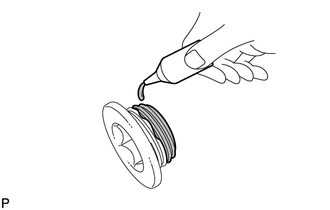
Apply adhesive to 3 or more threads of the taper screw plug.
Adhesive Toyota Genuine Adhesive 1344, Three Bond 1344 or equivalent -
Using a 10 mm hexagon wrench, install the taper screw plug.
- Torque:
- 15 N*m { 153 kgf*cm, 11 ft.*lbf }
-
-
CHECK NO. 1 CYLINDER TO TDC/COMPRESSION
-
Rotate the crankshaft clockwise 3 times or more, and check that the timing marks of the camshafts (1 dot mark each) align. If the timing marks of the camshafts do not align, repeat the "Install No. 3 and No. 4 Camshafts" and "Install No. 1 and No. 2 Camshafts" procedures.
-
-
INSTALL FUEL INJECTOR LH
-
INSTALL FUEL INJECTOR RH
-
INSTALL NOZZLE HOLDER GASKET LH
-
INSTALL CYLINDER HEAD COVER SUB-ASSEMBLY LH
-
INSTALL NOZZLE HOLDER SEAL LH
-
INSTALL OIL SEPARATOR ASSEMBLY
-
INSTALL NOZZLE HOLDER GASKET RH
-
INSTALL CYLINDER HEAD COVER SUB-ASSEMBLY RH
-
INSTALL NOZZLE HOLDER SEAL RH
-
INSTALL CYLINDER HEAD COVER SILENCER LH (w/ Intercooler)
-
INSTALL CYLINDER HEAD COVER SILENCER RH (w/ Intercooler)
-
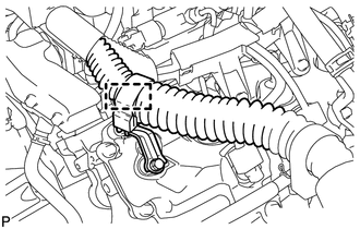
CONNECT NO. 3 VENTILATION HOSE
-
CONNECT NO. 2 VENTILATION HOSE
-
INSTALL VACUUM PUMP ASSEMBLY (w/ Intercooler)
-
INSTALL NO. 1 VACUUM TRANSMITTING PIPE SUB-ASSEMBLY
-
INSTALL NO. 1 VACUUM SWITCHING VALVE ASSEMBLY (w/ Intercooler)
-
INSTALL NO. 2 IDLER PULLEY BRACKET (w/ Viscous Heater)
-
INSTALL NO. 2 IDLER PULLEY (w/ Viscous Heater)
-
INSTALL INJECTION PIPE RH
-
CONNECT NO. 2 ENGINE WIRE
-
INSTALL FUEL FILTER TO INJECTION PUMP FUEL PIPE SUB-ASSEMBLY
-
INSTALL COMMON RAIL ASSEMBLY LH
-
INSTALL INJECTION PIPE LH
-
INSTALL NO. 6 INJECTION PIPE SUB-ASSEMBLY
-
INSTALL NO. 2 FUEL PIPE SUB-ASSEMBLY
-
CONNECT ENGINE WIRE
-
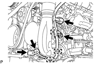
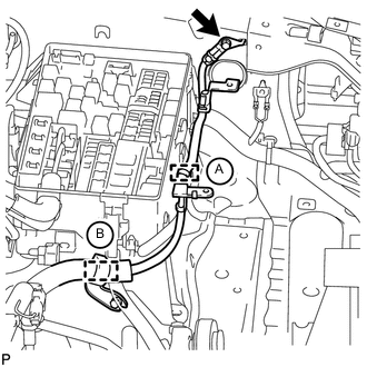
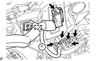
RH side:
-
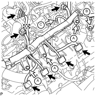
Install the engine wire harness protector with the 3 bolts labeled A.
-
Connect the 7 connectors.
-
Attach the wire harness clamp.
-
Install the wire harness bracket with the bolt labeled B.
-
Install the glow plug wire harness with the nut labeled C.
- Torque:
- 4.0 N*m { 41 kgf*cm, 35 in.*lbf }
-
Attach the 5 wire harness clamps and connect the 4 connectors.
-
-
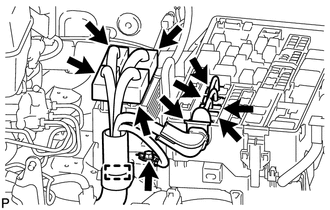
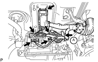
LH side:
-
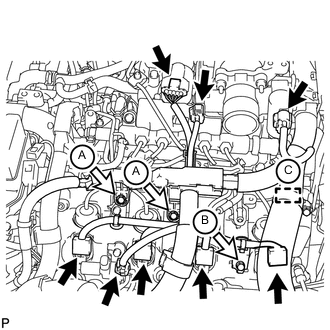
Install the engine wire harness protector with the 2 bolts labeled A.
-
Connect the 8 connectors.
-
Install the wire harness bracket with the bolt labeled B.
-
for RHD:
Connect the wire harness with the wire harness clamp holder labeled C.
-
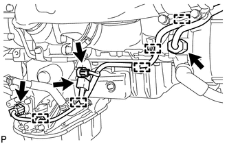
Attach the 3 wire harness clamps and connect the 2 connectors.
-
Attach the 3 wire harness clamps and connect the 4 connectors.
-
Connect the wire harness with the wire harness clamp holder labeled B.
-
Attach the ground wire clamp labeled A to the relay block side.
-
Install the ground wire to the body panel with the bolt.
- Torque:
- 8.4 N*m { 87 kgf*cm, 74 in.*lbf }
-
Connect the 4 connectors to the injector driver.
-
Install the ground wire with the bolt.
- Torque:
- 8.4 N*m { 86 kgf*cm, 74 in.*lbf }
-
Connect the wire harness holder to the relay block.
-
Connect the 4 connectors to the relay block.
-
Connect the wire harness with the wire harness clamp holder.
-
-
for RHD:
-
Connect the wire harness with the wire harness clamp holder.
-
Connect the ECM connector to the ECM.
-
Connect the wire harness with the wire harness clamp holder.
-
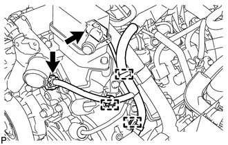
Attach the wire harness tab labeled A to the relay block.
-
Connect the 4 connectors to the relay block.
-
-
for LHD:
-
Connect the wire harness with the wire harness clamp holder.
-
Connect the ECM connector to the ECM.
-
Attach the wire harness tab labeled A to the relay block.
-
Connect the 4 connectors to the relay block.
-
-
-
CONNECT FUEL HOSE
-
INSTALL NO. 4 WATER BY-PASS PIPE
-
INSTALL NO. 3 WATER BY-PASS PIPE (w/o Viscous Heater)
-
INSTALL TUBE CONNECTOR TO FLEXIBLE HOSE TUBE (for Manual Transaxle)
-
INSTALL AIR TUBE SUB-ASSEMBLY LH
-
INSTALL CLUTCH HOSE (for Manual Transmission)
-
INSTALL AIR TUBE SUB-ASSEMBLY RH
-
INSTALL NO. 2 ENGINE OIL LEVEL DIPSTICK GUIDE
-
CONNECT WATER HOSE SUB-ASSEMBLY
-
INSTALL NO. 2 AIR CLEANER PIPE SUB-ASSEMBLY
-
INSTALL NO. 4 AIR TUBE
-
INSTALL NO. 2 AIR HOSE
-
INSTALL NO. 1 AIR CLEANER PIPE SUB-ASSEMBLY
-
INSTALL NO. 3 AIR TUBE
-
INSTALL NO. 1 AIR HOSE
-
INSTALL NO. 1 IDLER PULLEY BRACKET (w/ Viscous Heater)
-
INSTALL VISCOUS HEATER ASSEMBLY WITH MAGNET CLUTCH (w/ Viscous Heater)
-
INSTALL HEATER WATER PIPE SUB-ASSEMBLY (w/ Viscous Heater)
-
INSTALL NO. 2 COOL AIR INLET (w/o Intercooler)
-
INSTALL NO. 1 COOL AIR INLET (w/o Intercooler)
-
INSTALL INTERCOOLER ASSEMBLY (w/ Intercooler)
-
INSTALL FAN SHROUD WITH FAN
-
INSTALL OIL COOLER TUBE (for Automatic Transmission)
-
INSTALL V-RIBBED BELT
-
INSTALL NO. 3 IDLER PULLEY (w/ Viscous Heater)
-
INSTALL NO. 1 IDLER PULLEY (w/ Viscous Heater)
-
INSTALL V-RIBBED BELT (w/ Viscous Heater)
-
INSTALL VANE PUMP ASSEMBLY
-
INSTALL RADIATOR RESERVOIR ASSEMBLY
-
INSTALL NO. 1 OIL RESERVOIR BRACKET
-
INSTALL VANE PUMP OIL RESERVOIR ASSEMBLY
-
INSTALL INTAKE AIR CONNECTOR
-
TEMPORARILY INSTALL NO. 1 AIR CLEANER HOSE
-
INSTALL AIR CLEANER CAP SUB-ASSEMBLY
-
INSTALL NO. 3 ENGINE ROOM WIRE
-
ADD ENGINE OIL
-
BLEED AIR FROM FUEL SYSTEM
-
BLEED CLUTCH LINE
-
INSPECT FOR CLUTCH FLUID LEAK
-
CONNECT CABLE TO NEGATIVE BATTERY TERMINAL
Note
When disconnecting the cable, some systems need to be initialized after the cable is reconnected Click here.
-
Connect the cables to negative (-) main battery and sub-battery battery terminals.
-
-
ADD ENGINE COOLANT
-
INSPECT FOR FUEL LEAK
-
INSPECT FOR OIL LEAK
-
INSPECT FOR COOLANT LEAK
-
WARM UP ENGINE
Note
In order to bleed air from the chain tensioner, drive the vehicle with the engine at 3000 rpm for 60 seconds or more.
-
INSPECT FOR EXHAUST GAS LEAK
-
INSTALL NO. 1 ENGINE UNDER COVER SUB-ASSEMBLY
-
INSTALL FRONT FENDER SPLASH SHIELD SUB-ASSEMBLY RH
-
INSTALL FRONT FENDER SPLASH SHIELD SUB-ASSEMBLY LH
-
INSTALL FRONT FENDER APRON SEAL REAR LH
-
INSTALL FRONT FENDER APRON SEAL FRONT LH
-
INSTALL FRONT FENDER APRON SEAL REAR RH
-
INSTALL FRONT FENDER APRON SEAL FRONT RH
-
INSTALL FRONT WHEEL
-
INSTALL NO. 1 ENGINE COVER SUB-ASSEMBLY (w/ Intercooler)
-
INSTALL COWL TOP VENTILATOR LOUVER SUB-ASSEMBLY
-
INSTALL HOOD TO COWL TOP SEAL
-
INSTALL FRONT WIPER ARM RH
-
INSTALL FRONT WIPER ARM LH
-
INSTALL FRONT FENDER MAIN SEAL RH
-
INSTALL FRONT FENDER MAIN SEAL LH
-
INSTALL UPPER RADIATOR SUPPORT SEAL
-
INSPECT ENGINE IDLE SPEED
-
INSPECT MAXIMUM ENGINE SPEED
-
CHECK ENGINE OIL LEVEL
-
INSPECT ENGINE COOLANT LEVEL IN RESERVOIR