ECD SYSTEM(w/o DPF), Diagnostic DTC:P1251
| DTC Code | DTC Name |
|---|---|
| P1251 | Turbocharger / Supercharger Overboost Condition (Too High) |
DESCRIPTION
| DTC Detection Drive Pattern | DTC Detection Condition | Trouble Area |
|---|---|---|
| Vehicle being driven | The turbo motor driver detects an overcurrent caused by the DC motor being stuck (1 trip detection logic). |
|
| DTC No. | Data List |
|---|---|
| P1251 |
|
If DTC P1251 is stored, the following symptoms may appear:
-
VN turbo vane stuck closed malfunction
-
Vehicle surge when driving with full load
-
Sudden lack of power due to power being limited
CAUTION / NOTICE / HINT
Tech Tips
Read freeze frame data using the intelligent tester. Freeze frame data records the engine condition when malfunctions are detected. When troubleshooting, freeze frame data can help determine if the vehicle was moving or stationary, if the engine was warmed up or not, and other data from the time the malfunction occurred.
Note
After replacing the ECM, the new ECM needs registration (See page ) and initialization Click here.
PROCEDURE
-
CHECK ANY OTHER DTCS OUTPUT (IN ADDITION TO DTC P1251)
-
Connect the intelligent tester to the DLC3.
-
Turn the ignition switch to ON and turn the tester on.
-
Enter the following menus: Powertrain / Engine / DTC.
-
Read the DTCs.
Result Display (DTC Output) Proceed to P1251 A P1251 and other DTCs B
B 
GO TO DTC CHART Click here
A 
-
-
INSPECT TURBOCHARGER SUB-ASSEMBLY (for Bank 1 and/or Bank 2)
-
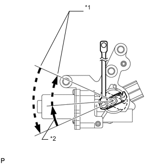
*1 Idling to ignition switch off *2 Ignition switch ON to idling Check the motor movement when turning the ignition switch to ON, when starting the engine and then when turning the ignition switch off.
OK Motor moves as shown in the illustration.
NG 
INSPECT TURBO MOTOR DRIVER (POWER SOURCE CIRCUIT) Click here
OK
-
-
CHECK WHETHER DTC OUTPUT RECURS (DTC P1251)
-
Connect the intelligent tester to the DLC3.
-
Turn the ignition switch to ON and turn the tester on.
-
Enter the following: Powertrain / Engine / DTC / Clear.
-
Clear DTCs Click here.
-
Turn the ignition switch off.
-
Start the engine and warm it up.
-
Drive the vehicle.
-
Enter the following menus: Powertrain / Engine / DTC.
-
Read the DTCs.
Result Display (DTC Output) Proceed to P1251 A No output B
A
REPLACE ECM Click here
B
END
-
-
INSPECT TURBO MOTOR DRIVER (POWER SOURCE CIRCUIT)
-
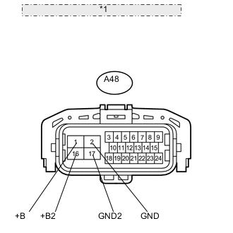
*1 Front view of wire harness connector: (to Turbo Motor Driver) Disconnect the turbo motor driver connector.
-
Measure the voltage according to the value(s) in the table below.
Standard Voltage Tester Connection Condition Specified Condition A48-1 (+B) - A48-2 (GND) Engine switch on (IG) 11 to 14 V A48-16 (+B2) - A48-17 (GND2) Engine switch on (IG) 11 to 14 V -
Measure the resistance according to the value(s) in the table below.
Standard Resistance Tester Connection Condition Specified Condition A48-2 (GND) - Body ground Always Below 1 Ω A48-17 (GND2) - Body ground Always Below 1 Ω
NG
REPAIR OR REPLACE HARNESS OR CONNECTOR Click here
OK
-
-
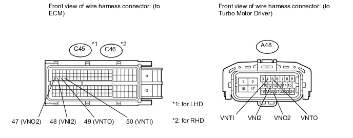
CHECK HARNESS AND CONNECTOR (TURBO MOTOR DRIVER - ECM)
-
Disconnect the turbo motor driver connector.
-
Disconnect the ECM connector.
-
Measure the resistance according to the value(s) in the table below.
Standard Resistance (Check for Open) for LHD Tester Connection Condition Specified Condition C45-49 (VNTO) - A48-5 (VNTO) Always Below 1 Ω C45-50 (VNTI) - A48-4 (VNTI) Always Below 1 Ω C45-47 (VNO2) - A48-20 (VNO2) Always Below 1 Ω C45-48 (VNI2) - A48-11 (VNI2) Always Below 1 Ω for RHD Tester Connection Condition Specified Condition C46-49 (VNTO) - A48-5 (VNTO) Always Below 1 Ω C46-50 (VNTI) - A48-4 (VNTI) Always Below 1 Ω C46-47 (VNO2) - A48-20 (VNO2) Always Below 1 Ω C46-48 (VNI2) - A48-11 (VNI2) Always Below 1 Ω Standard Resistance (Check for Short) for LHD Tester Connection Condition Specified Condition C45-49 (VNTO) or A48-5 (VNTO) - Body ground Always 10 kΩ or higher C45-50 (VNTI) or A48-4 (VNTI) - Body ground Always 10 kΩ or higher C45-47 (VNO2) or A48-20 (VNO2) - Body ground Always 10 kΩ or higher C45-48 (VNI2) or A48-11 (VNI2) - Body ground Always 10 kΩ or higher for RHD Tester Connection Condition Specified Condition C46-49 (VNTO) or A48-5 (VNTO) - Body ground Always 10 kΩ or higher C46-50 (VNTI) or A48-4 (VNTI) - Body ground Always 10 kΩ or higher C46-47 (VNO2) or A48-20 (VNO2) - Body ground Always 10 kΩ or higher C46-48 (VNI2) or A48-11 (VNI2) - Body ground Always 10 kΩ or higher
NG
REPAIR OR REPLACE HARNESS OR CONNECTOR Click here
OK
-
-
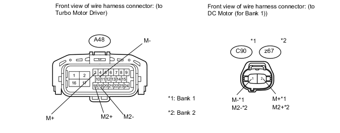
CHECK HARNESS AND CONNECTOR (DC MOTOR - TURBO MOTOR DRIVER)
-
Disconnect the DC motor (for Bank 1) connector.
-
Disconnect the DC motor (for Bank 2) connector.
-
Disconnect the turbo motor driver connector.
-
Measure the resistance according to the value(s) in the table below.
Standard Resistance (Check for Open) for Bank 1 Tester Connection Condition Specified Condition C90-1 (M-) - A48-10 (M-) Always Below 1 Ω C90-2 (M+) - A48-3 (M+) Always Below 1 Ω for Bank 2 Tester Connection Condition Specified Condition z67-1 (M2-) - A48-19 (M2-) Always Below 1 Ω z67-2 (M2+) - A48-18 (M2+) Always Below 1 Ω Standard Resistance (Check for Short) for Bank 1 Tester Connection Condition Specified Condition C90-1 (M-) or A48-10 (M-) - Body ground Always 10 kΩ or higher C90-2 (M+) or A48-3 (M+) - Body ground Always 10 kΩ or higher for Bank 2 Tester Connection Condition Specified Condition z67-1 (M2-) or A48-19 (M2-) - Body ground Always 10 kΩ or higher z67-2 (M2+) or A48-18 (M2+) - Body ground Always 10 kΩ or higher
NG
REPAIR OR REPLACE HARNESS OR CONNECTOR Click here
OK
-
-
REPLACE TURBO MOTOR DRIVER (for Bank 1 and/or Bank 2)
-
Replace the turbo motor driver (for Bank 1 and/or Bank 2) Click here.
NEXT
-
-
CHECK WHETHER DTC OUTPUT RECURS (DTC P1251)
-
Connect the intelligent tester to the DLC3.
-
Turn the ignition switch to ON and turn the tester on.
-
Enter the following menus: Powertrain / Engine / DTC / Clear.
-
Clear the DTCs Click here.
-
Turn the ignition switch off.
-
Start the engine and warm it up.
-
Drive the vehicle.
-
Enter the following menus: Powertrain / Engine / DTC.
-
Read the DTCs.
Result Display (DTC Output) Proceed to P1251 A No output B
B
END
A
-
-
REPLACE TURBOCHARGER SUB-ASSEMBLY (for Bank 1 and/or Bank 2) (DC MOTOR)
-
Replace the turbocharger sub-assembly (for Bank 1 or Bank 2) Click here.
NEXT
CONFIRM WHETHER MALFUNCTION HAS BEEN SUCCESSFULLY REPAIRED Click here
-
-
REPAIR OR REPLACE HARNESS OR CONNECTOR
NEXT
CONFIRM WHETHER MALFUNCTION HAS BEEN SUCCESSFULLY REPAIRED Click here
-
REPLACE ECM
-
Replace the ECM Click here.
NEXT
-
-
CONFIRM WHETHER MALFUNCTION HAS BEEN SUCCESSFULLY REPAIRED
-
Connect the intelligent tester to the DLC3.
-
Clear the DTCs Click here.
-
Turn the ignition switch off.
-
Start the engine and warm it up.
-
Run the engine with a heavy load at a mid to high engine speed.
-
Confirm that the DTC is not output again.
Tech Tips
Perform the following procedure using the tester to determine whether or not the DTC judgment has been carried out.
-
Enter the following menus: Powertrain / Engine / Utility / All Readiness.
-
Input DTC P1251.
-
Check that STATUS is NORMAL. If STATUS is INCOMPLETE or UNKNOWN, increase the time spent running the engine with a heavy load at a mid to high engine speed.
-
NEXT
END
-