ECD SYSTEM(w/o DPF), Diagnostic DTC:P0046, P0047, P0048, P004B, P004C, P004D
| DTC Code | DTC Name |
|---|---|
| P0046 | Turbocharger / Supercharger Boost Control Solenoid Circuit Range / Performance |
| P0047 | Turbocharger/Supercharger Boost Control "A" Circuit Low |
| P0048 | Turbocharger/Supercharger Boost Control "A" Circuit High |
| P004B | Turbocharger/Supercharger Boost Control Solenoid "B" Circuit Range/Performance |
| P004C | Turbocharger/Supercharger Boost Control Solenoid "B" Circuit Low |
| P004D | Turbocharger/Supercharger Boost Control Solenoid "B" Circuit High |
DESCRIPTION
These DTCs indicates that the DC motor of the turbocharger is malfunctioning. The ECM monitors the DC motor current to detect an open or short in the DC motor circuit. If the current meets the criteria, the ECM sets a DTC and illuminates the MIL immediately.
The DC motor is used to operate the nozzle vane of the turbocharger. The nozzle vane opens and closes to change the velocity of exhaust emissions in order to control the turbo pressure. The ECM varies the duty-cycle of the DC motor in accordance with the driving condition.
If the nozzle vane is stuck closed (DC motor stuck off), the drivability may deteriorate at wide open throttle. If the nozzle vane is stuck open (DC motor stuck on), the drivability may deteriorate at intermediate throttle or the engine power may be insufficient.
| DTC Detection Drive Pattern | DTC Detection Condition | Trouble Area |
|---|---|---|
| Ignition switch ON for 5 seconds | Either of the following conditions are met when the motor is driving (1 trip detection logic):
|
|
| DTC Detection Drive Pattern | DTC Detection Condition | Trouble Area |
|---|---|---|
| Ignition switch ON for 1 second | Both of following conditions are met for 1 second or more when the motor is driving (1 trip detection logic):
|
|
| DTC Detection Drive Pattern | DTC Detection Condition | Trouble Area |
|---|---|---|
| Ignition switch ON for 1 second | DC motor current is 6.5 A or more for 0.5 seconds or more when the motor is operating (1 trip detection logic). |
|
Tech Tips
If DTC P0046, P0047, P0048, P004B, P004C and/or P004D is stored, the following symptoms may appear.
-
Stuck closed malfunction:
-
Vehicle surge when driving with full load
-
Stuck open malfunction:
-
Lack of power
-
Vehicle surge or hesitation under light or medium load
-
White smoke
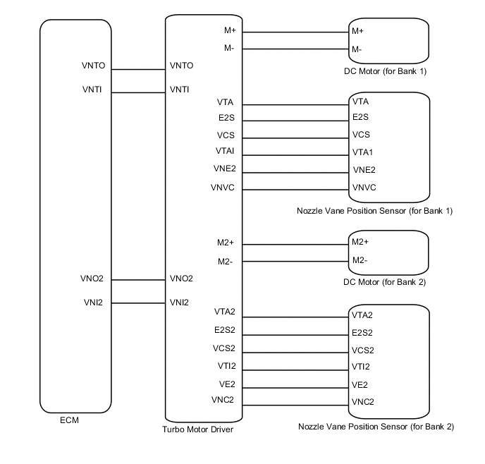
WIRING DIAGRAM
| *a | DC Motor |
| *b | (Turbocharger sub-assembly) (for Bank 1) |
| *c | (Turbocharger sub-assembly) (for Bank 2) |
| *d | Turbo Motor Driver |
CAUTION / NOTICE / HINT
Tech Tips
Read freeze frame data using the intelligent tester. Freeze frame data records the engine condition when malfunctions are detected. When troubleshooting, freeze frame data can help determine if the vehicle was moving or stationary, if the engine was warmed up or not, and other data from the time the malfunction occurred.
PROCEDURE
-
INSPECT TURBOCHARGER SUB-ASSEMBLY (DC MOTOR) (for Bank 1 or Bank 2)
-
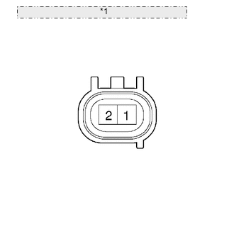
*1 Component without harness connected: (DC Motor) Disconnect the DC motor connector.
-
Measure the resistance according to the value(s) in the table below.
Standard Resistance for Bank 1 Tester Connection Condition Specified Condition 1 (M-) - 2 (M+) Always 1 to 100 Ω Standard Resistance for Bank 2 Tester Connection Condition Specified Condition 1 (M2-) - 2 (M2+) Always 1 to 100 Ω
NG 
REPLACE TURBOCHARGER SUB-ASSEMBLY (for Bank 1 or Bank 2) Click here
OK 
-
-
CHECK HARNESS AND CONNECTOR (DC MOTOR - TURBO MOTOR DRIVER)
-
Disconnect the DC motor (for Bank 1) connector.
-
Disconnect the DC motor (for Bank 2) connector.
-
Disconnect the turbo motor driver connector.
-
Measure the resistance according to the value(s) in the table below.
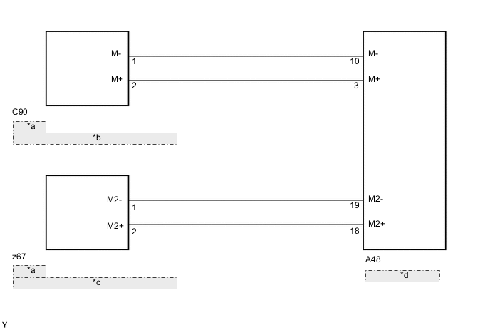
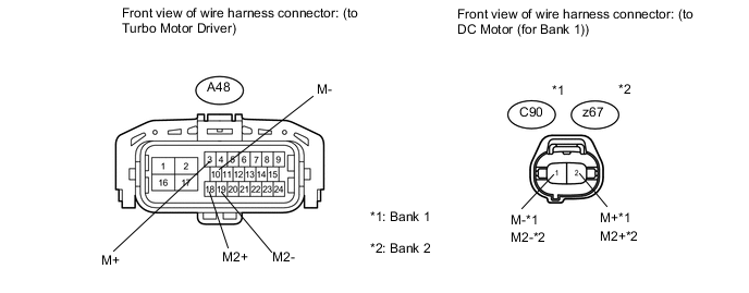
Standard Resistance (Check for Open) for Bank 1 Tester Connection Condition Specified Condition C90-1 (M-) - A48-10 (M-) Always Below 1 Ω C90-2 (M+) - A48-3 (M+) Always Below 1 Ω for Bank 2 Tester Connection Condition Specified Condition z67-1 (M2-) - A48-19 (M2-) Always Below 1 Ω z67-2 (M2+) - A48-18 (M2+) Always Below 1 Ω Standard Resistance (Check for Short) for Bank 1 Tester Connection Condition Specified Condition C90-1 (M-) or A48-10 (M-) - Body ground Always 10 kΩ or higher C90-2 (M+) or A48-3 (M+) - Body ground Always 10 kΩ or higher for Bank 2 Tester Connection Condition Specified Condition z67-1 (M2-) or A48-19 (M2-) - Body ground Always 10 kΩ or higher z67-2 (M2+) or A48-18 (M2+) - Body ground Always 10 kΩ or higher
NG
REPAIR OR REPLACE HARNESS OR CONNECTOR Click here
OK
-
-
INSPECT TURBOCHARGER SUB - ASSEMBLY
-
Connect the intelligent tester to the DLC3.
-
Turn the ignition switch to ON and turn the tester on.
-
Start the engine and warm up.
-
Move the shift lever to 3rd and accelerate the vehicle with the accelerator fully open.
-
Stop the vehicle.
-
Enter the following menus: Powertrain / Engine / DTC.
-
Read the DTCs.
Result Display (DTC Output) Proceed to DTC P0046, P0047, P0048, P004B, P004C and/or P004D are output A No DTC output B Tech Tips
-
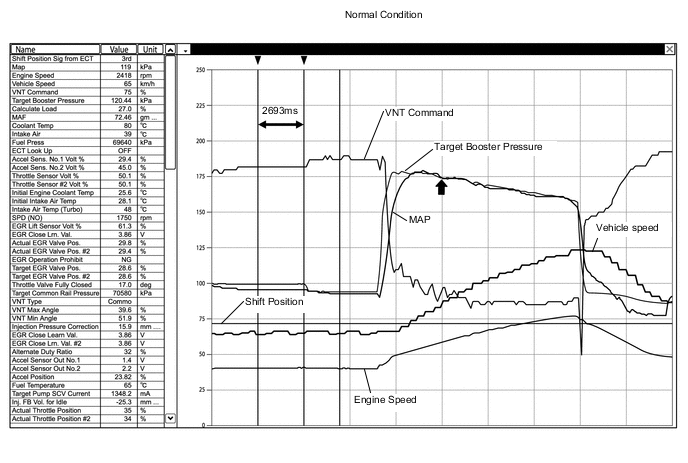
A snapshot can be used to compare vehicle data from the time of the malfunction to normal data and is very useful for troubleshooting.
-
"Target Booster Pressure" and "MAP" in the snapshot can be used to check the operation of the turbocharger. If "MAP" does not follow "Target Booster Pressure", the turbocharger nozzle vane may be stuck or the movement may be irregular.
-
When the engine speed is 2500 to 3000 rpm with the accelerator pedal fully depressed, "MAP" is within +/- 10 kPa*of "Target Booster Pressure" (not immediately after beginning of acceleration).
-
*If the turbocharger pressure does not reach a specified value, it cannot be determined whether the system is normal by checking whether "MAP" is within +/-10 kPa of "Target Booster Pressure".
Tech Tips
Compare "MAP" with "Target Booster Pressure" at the point indicated by the arrow (↑) in the illustration.
-
A
REPLACE TURBOCHARGER SUB-ASSEMBLY (for Bank 1 or Bank 2) Click here
B
-
-
INSPECT TURBO MOTOR DRIVER
-
Connect the intelligent tester to the DLC3.
-
Clear the DTCs Click here.
-
Turn the engine switch off.
-
Remove the rear fender splash shield sub-assembly RH.
-
Remove the front fender liner LH.
-
Disconnect the turbo motor driver connector.
-
Reconnect the turbo motor driver connector.
-
Turn the engine switch on (IG) and turn the tester on.
-
After starting the engine, idle it for 5 seconds.
-
Enter the following menus: Powertrain / Engine / DTC.
-
Read the DTCs.
Result Display (DTC Output) Proceed to DTC is output A DTC is not output B
B 
END
A
-
-
REPLACE TURBO MOTOR DRIVER
-
Replace the turbo motor driver Click here.
Note
Make sure that foreign matter does not enter the connector(s) when replacing parts.
NEXT
CONFIRM WHETHER MALFUNCTION HAS BEEN SUCCESSFULLY REPAIRED Click here
-
-
REPLACE TURBOCHARGER SUB-ASSEMBLY (for Bank 1 or Bank 2)
-
Replace the turbocharger sub-assembly (for Bank 1 or Bank 2) Click here.
NEXT
CONFIRM WHETHER MALFUNCTION HAS BEEN SUCCESSFULLY REPAIRED Click here
-
-
REPAIR OR REPLACE HARNESS OR CONNECTOR
NEXT
-
CONFIRM WHETHER MALFUNCTION HAS BEEN SUCCESSFULLY REPAIRED
-
Connect the intelligent tester to the DLC3.
-
Clear the DTCs Click here.
-
Turn the ignition switch off.
-
Turn the ignition switch to ON for 5 seconds or more.
-
Enter the following menus: Powertrain / Engine / DTC.
-
Confirm that the DTC is not output again.
NEXT
END
-