ECD SYSTEM(w/ DPF) VC Output Circuit
DESCRIPTION
The ECM constantly generates 5 V of power from the battery voltage supplied to the +B (BATT) terminal to operate the microprocessor. The ECM also provides this power to the sensors through the VC output circuit.
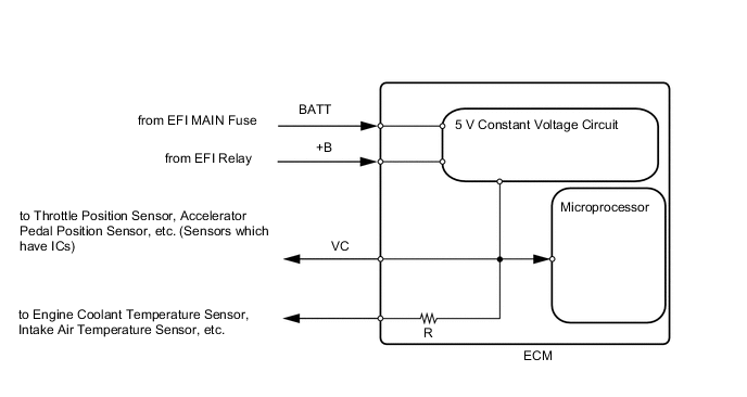
When the VC circuit is short-circuited, the microprocessor in the ECM and sensors that are supplied with power through the VC circuit are inactivated because the power is not supplied from the VC circuit. Under this condition, the system does not start up and the MIL does not illuminate even if the system malfunctions.
Tech Tips
Under normal conditions, the MIL is illuminated for several seconds when the engine switch is first turned on (IG). The MIL goes off when the engine is started.
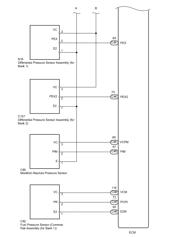
WIRING DIAGRAM

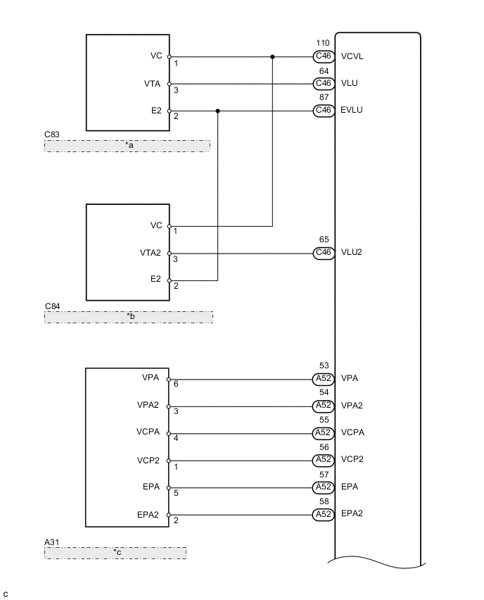
| *a | Throttle Position Sensor (Diesel Throttle Body Assembly (for Bank 1)) |
| *b | Throttle Position Sensor (Diesel Throttle Body Assembly (for Bank 2)) |
| *c | Accelerator Pedal Position Sensor (Accelerator Pedal Rod Assembly) |

| *a | Throttle Position Sensor (Diesel Throttle Body Assembly (for Bank 1)) |
| *b | Throttle Position Sensor (Diesel Throttle Body Assembly (for Bank 2)) |
| *c | Accelerator Pedal Position Sensor (Accelerator Pedal) |
CAUTION / NOTICE / HINT
Note
After replacing the ECM, the new ECM needs registration (See page ) and initialization Click here.
PROCEDURE
-
CHECK MIL
-
Check that the Malfunction Indicator Lamp (MIL) lights up when turning the engine switch on (IG).
Result Result Proceed to MIL illuminates A MIL does not illuminate B
A 
END
B 
-
-
CHECK COMMUNICATION BETWEEN GTS AND ECM
-
Connect the GTS to the DLC3.
-
Turn the engine switch on (IG) and GTS on.
-
Check the communication between the GTS and ECM.
Result Result Proceed to Communication is possible A Communication is not possible B
A
GO TO MIL CIRCUIT Click here
B
-
-
CHECK MIL (THROTTLE POSITION SENSOR (for Bank 1))
-
Disconnect the C83 throttle position sensor (for Bank 1) connector.
-
Turn the engine switch on (IG).
-
Check the MIL.
Result Result Proceed to MIL illuminates A MIL does not illuminate B -
Reconnect the C83 throttle position sensor (for Bank 1) connector.
A
REPLACE DIESEL THROTTLE BODY ASSEMBLY (for Bank 1) Click here
B
-
-
CHECK MIL (THROTTLE POSITION SENSOR (for Bank 2))
-
Disconnect the C84 throttle position sensor (for Bank 2) connector.
-
Turn the engine switch on (IG).
-
Check the MIL.
Result Result Proceed to MIL illuminates A MIL does not illuminate B -
Reconnect the C84 throttle position sensor (for Bank 2) connector.
A
REPLACE DIESEL THROTTLE BODY ASSEMBLY (for Bank 2) Click here
B
-
-
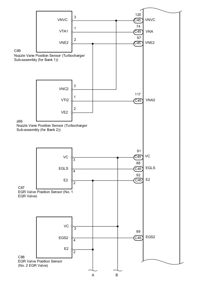
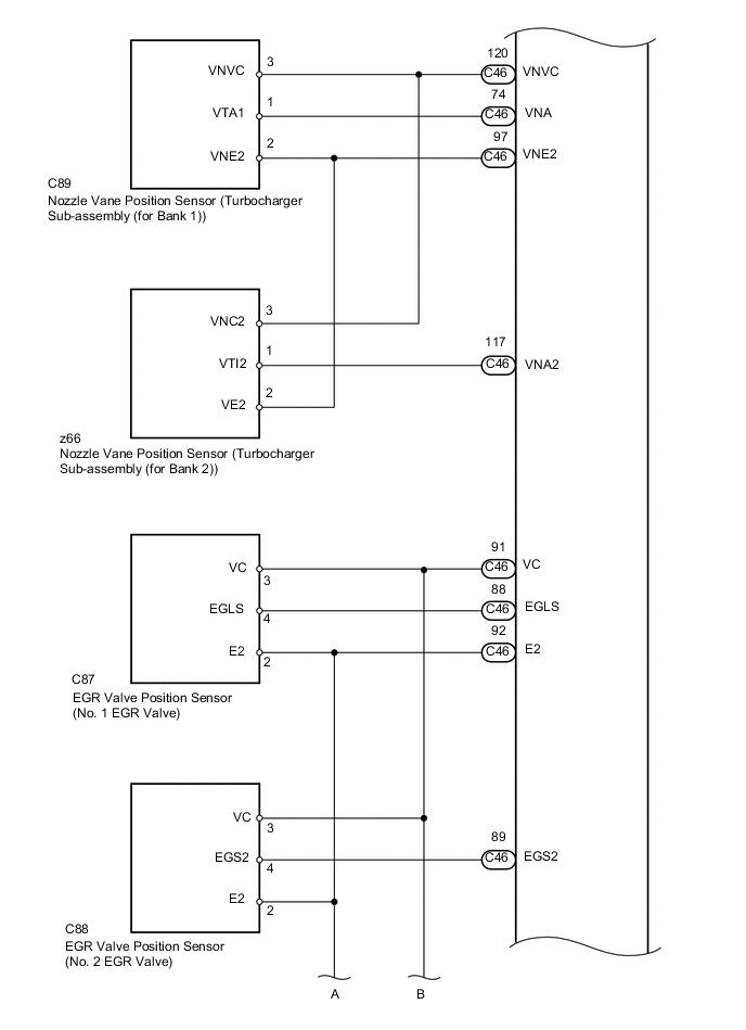
CHECK MIL (NO. 1 EGR VALVE POSITION SENSOR)
-
Disconnect the C87 No. 1 EGR valve connector.
-
Turn the engine switch on (IG).
-
Check the MIL.
Result Result Proceed to MIL illuminates A MIL does not illuminate B -
Reconnect the C87 No. 1 EGR valve connector.
A
REPLACE NO. 1 EGR VALVE ASSEMBLY Click here
B
-
-
CHECK MIL (NO. 2 EGR VALVE POSITION SENSOR)
-
Disconnect the C88 No. 2 EGR valve connector.
-
Turn the engine switch on (IG).
-
Check the MIL.
Result Result Proceed to MIL illuminates A MIL does not illuminate B -
Reconnect the C88 No. 2 EGR valve connector.
A
REPLACE NO. 2 EGR VALVE ASSEMBLY Click here
B
-
-
CHECK MIL (ACCELERATOR PEDAL POSITION SENSOR)
-
Disconnect the A31 accelerator pedal position sensor connector.
-
Turn the engine switch on (IG).
-
Check the MIL.
Result Result Proceed to MIL illuminates A MIL does not illuminate B -
Reconnect the A31 accelerator pedal position sensor connector.
A
REPLACE ACCELERATOR PEDAL ROD ASSEMBLY Click here
B
-
-
CHECK MIL (MANIFOLD ABSOLUTE PRESSURE SENSOR)
-
Disconnect the C80 manifold absolute pressure sensor connector.
-
Turn the engine switch on (IG).
-
Check the MIL.
Result Result Proceed to MIL illuminates A MIL does not illuminate B -
Reconnect the C80 manifold absolute pressure sensor connector.
A
REPLACE MANIFOLD ABSOLUTE PRESSURE SENSOR Click here
B
-
-
CHECK MIL (FUEL PRESSURE SENSOR)
-
Disconnect the C82 fuel pressure sensor connector.
-
Turn the engine switch on (IG).
-
Check the MIL.
Result Result Proceed to MIL illuminates A MIL does not illuminate B -
Reconnect the C82 fuel pressure sensor connector.
A
REPLACE COMMON RAIL (for Bank 1) Click here
B
-
-
CHECK MIL (DIFFERENTIAL PRESSURE SENSOR ASSEMBLY (for Bank 1))
-
Disconnect the N16 differential pressure sensor assembly (for Bank 1) connector.
-
Turn the engine switch on (IG).
-
Check the MIL.
Result Result Proceed to MIL illuminates A MIL does not illuminate B -
Reconnect the N16 differential pressure sensor assembly (for Bank 1) connector.
A
REPLACE DIFFERENTIAL PRESSURE SENSOR (for Bank 1) Click here
B
-
-
CHECK MIL (DIFFERENTIAL PRESSURE SENSOR ASSEMBLY (for Bank 2))
-
Disconnect the C157 differential pressure sensor assembly (for Bank 2) connector.
-
Turn the engine switch on (IG).
-
Check the MIL.
Result Result Proceed to MIL illuminates A MIL does not illuminate B -
Reconnect the C157 differential pressure sensor assembly (for Bank 2) connector.
A
REPLACE DIFFERENTIAL PRESSURE SENSOR (for Bank 2) Click here
B
-
-
CHECK MIL (NOZZLE VANE POSITION SENSOR (for Bank 1))
-
Disconnect the C89 nozzle vane position sensor (for Bank 1) connector.
-
Turn the engine switch on (IG).
-
Check the MIL.
Result Result Proceed to MIL illuminates A MIL does not illuminate B -
Reconnect the C89 nozzle vane position sensor (for Bank 1) connector.
A
REPLACE TURBOCHARGER SUB-ASSEMBLY (for Bank 1) Click here
B
-
-
CHECK MIL (NOZZLE VANE POSITION SENSOR (for Bank 2))
-
Disconnect the z66 nozzle vane position sensor (for Bank 2) connector.
-
Turn the engine switch on (IG).
-
Check the MIL.
Result Result Proceed to MIL illuminates A MIL does not illuminate B -
Reconnect the z66 nozzle vane position sensor (for Bank 2) connector.
A
REPLACE TURBOCHARGER SUB-ASSEMBLY (for Bank 2) Click here
B
-
-
CHECK HARNESS AND CONNECTOR
-
Disconnect the throttle position sensor (for Bank 1) connector.
-
Disconnect the throttle position sensor (for Bank 2) connector.
-
Disconnect the No. 1 EGR valve connector.
-
Disconnect the No. 2 EGR valve connector.
-
Disconnect the accelerator pedal position sensor connector.
-
Disconnect the manifold absolute pressure sensor connector.
-
Disconnect the fuel pressure sensor connector.
-
Disconnect the differential pressure sensor assembly (for Bank 1) connector.
-
Disconnect the differential pressure sensor assembly (for Bank 2) connector.
-
Disconnect the nozzle vane position sensor (for Bank 1) connector.
-
Disconnect the nozzle vane position sensor (for Bank 2) connector.
-
Disconnect the ECM connectors.
-
Measure the resistance according to the value(s) in the table below.
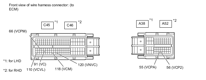
Standard Resistance (Check for Short) for LHD Tester Connection Condition Specified Condition C45-91 (VC) - Body ground Always 10 kΩ or higher C45-110 (VCVL) - Body ground Always 10 kΩ or higher C45-118 (VCM) - Body ground Always 10 kΩ or higher C45-120 (VNVC) - Body ground Always 10 kΩ or higher C45-66 (VCPM) - Body ground Always 10 kΩ or higher A38-55 (VCPA) - Body ground Always 10 kΩ or higher A38-56 (VCP2) - Body ground Always 10 kΩ or higher for RHD Tester Connection Condition Specified Condition C46-91 (VC) - Body ground Always 10 kΩ or higher C46-110 (VCVL) - Body ground Always 10 kΩ or higher C46-118 (VCM) - Body ground Always 10 kΩ or higher C46-120 (VNVC) - Body ground Always 10 kΩ or higher C46-66 (VCPM) - Body ground Always 10 kΩ or higher A52-55 (VCPA) - Body ground Always 10 kΩ or higher A52-56 (VCP2) - Body ground Always 10 kΩ or higher -
Reconnect the throttle position sensor (for Bank 1) connector.
-
Reconnect the throttle position sensor (for Bank 2) connector.
-
Reconnect the No. 1 EGR valve connector.
-
Reconnect the No. 2 EGR valve connector.
-
Reconnect the accelerator pedal position sensor connector.
-
Reconnect the manifold absolute pressure sensor connector.
-
Reconnect the fuel pressure sensor connector.
-
Reconnect the differential pressure sensor assembly (for Bank 1) connector.
-
Reconnect the differential pressure sensor assembly (for Bank 2) connector.
-
Reconnect the nozzle vane position sensor (for Bank 1) connector.
-
Reconnect the nozzle vane position sensor (for Bank 2) connector.
-
Reconnect the ECM connectors.
OK
REPLACE ECM Click here
NG
REPAIR OR REPLACE HARNESS OR CONNECTOR
-