SFI SYSTEM, Diagnostic DTC:P2445
| DTC Code | DTC Name |
|---|---|
| P2445 | Secondary Air Injection System Pump Stuck Off Bank1 |
DESCRIPTION
Refer to P0412 Click here.
| DTC No. | DTC Detection Condition | Trouble Area |
|---|---|---|
| P2445 | Secondary air pressure is below 1 kPa (8 mmHg) despite the ECM commanding the air pump to turn on (2 trip detection logic). |
|
| When secondary air injection is turned from off to on, the change in the secondary air injection pressure is less than 5 kPa (2 trip detection logic). |
MONITOR DESCRIPTION
The ECM monitors the pressure in the secondary air passage using the pressure sensor located on the emission control valve set of the secondary air injection system. The sensor measures the pressure in the secondary air passage and transmits a signal to the ECM.
If a malfunction is detected, the ECM illuminates the MIL and stores a DTC.
Example:
DTC P2445 mainly indicate a malfunction in which the air pump is stuck off.
WIRING DIAGRAM
Refer to DTC P0412 Click here.
CAUTION / NOTICE / HINT
Tech Tips
-
By using the GTS to perform the Secondary Air Injection Check operation in the System Check, the air-fuel ratio and the pressure in the secondary air injection system passage can be checked while the secondary air injection system is operating. This helps technicians to troubleshoot the system when it malfunctions. Furthermore, pending codes also can be checked by performing Utility / Secondary Air Injection Check / Automatic Mode after the repair.
-
Read freeze frame data using the GTS. Freeze frame data records the engine condition when malfunctions are detected. When troubleshooting, freeze frame data can help determine if the vehicle was moving or stationary, if the engine was warmed up or not, if the air-fuel ratio was lean or rich, and other data from the time the malfunction occurred.
PROCEDURE
-
CHECK FOR ANY OTHER DTCS OUTPUT (IN ADDITION TO DTC P2445)
-
Connect the GTS to the DLC3.
-
Turn the ignition switch to ON.
-
Turn the GTS on.
-
Enter the following menus: Powertrain / Engine and ECT / Trouble Codes.
-
Read the DTCs.
Result Result Proceed to P2445 is output A P2445 and P0418 are output B P2445 and other DTCs (except P0418) are output C Tech Tips
If any DTCs other than P0418 and P2445 are output, troubleshoot those DTCs first.
B 
GO TO AIR PUMP INSPECTION PROCEDURE Click here
C
GO TO DTC CHART Click here
A 
-
-
CHECK FREEZE FRAME DATA (AIR PUMP FREEZE, AIR SWITCHING VALVE FREEZEAND AIR SWITCHING VALVE2 FREEZE)
-
Connect the GTS to the DLC3.
-
Turn the ignition switch to ON and turn the GTS on.
-
Read the values of Air Pump Freeze, Air Switching Valve Freeze and Air Switching Valve2 Freeze from the freeze frame data recorded previously.
-
Referring to the following table, proceed to the appropriate step according to the result of the data reading.
Result Result Proceed to Air Pump Freeze Air Switching Valve Freeze Air Switching Valve2 Freeze OFF OFF OFF B Except above A
B 
PERFORM ACTIVE TEST USING GTS (SECONDARY AIR INJECTION SYSTEM OPERATION) Click here
A
-
-
PERFORM ACTIVE TEST USING GTS (ACTIVATE THE AIR PUMP HEATER)
-
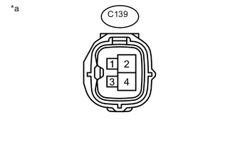
Text in Illustration *a Front view of wire harness connector
(to Air Pump Assembly)
Disconnect the air pump connector.
-
Connect the GTS to the DLC3.
-
Turn the ignition switch to ON and turn the GTS on.
-
Enter the following menus: Powertrain / Engine and ECT/ Active Test / Activate the Air Pump Heater.
-
Measure the voltage according to the value(s) in the table below.
Tester Connection Condition Specified Condition C139-1 (APH+) - Body ground Activate the Air Pump Heater is ON 11 to 14 V -
Reconnect the air pump connector.
NG
INSPECT AIR PUMP HEATER RELAY (AIR PMP HTR) Click here
OK
-
-
INSPECT AIR PUMP ASSEMBLY (HEATER RESISTANCE)
-
Inspect the air pump assembly Click here.
NG
REPLACE AIR PUMP ASSEMBLY Click here
OK
-
-
INSPECT AIR PUMP HEATER RELAY (AIR PMP HTR)
-
Inspect the air pump heater relay (AIR PMP HTR) Click here.
NG
REPLACE AIR PUMP HEATER RELAY (AIR PMP HTR)
OK
-
-
CHECK AIR PUMP HEATER RELAY (AIR PMP HTR) (POWER SOURCE)
-
Remove the air pump heater relay (AIR PMP HTR).
-
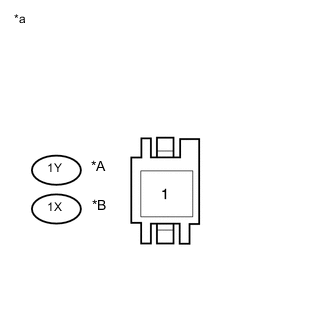
Text in Illustration *A for LHD: *B for RHD: *a Front view of wire harness connector (to Integration Relay) Measure the voltage according to the value(s) in the table below.
Standard Voltage for LHD: Tester Connection Condition Specified Condition 1Y-1 - Body ground Always 11 to 14 V for RHD: Tester Connection Condition Specified Condition 1X-1 - Body ground Always 11 to 14 V -
Reinstall the air pump heater relay (AIR PMP HTR).
NG
REPAIR OR REPLACE HARNESS OR CONNECTOR
OK
-
-
CHECK HARNESS AND CONNECTOR (AIR PUMP - AIR PUMP HEATER RELAY (AIR PMP HTR), BODY GROUND)
-
Remove the integration relay (AIR PMP HTR).
-
Disconnect the air pump connector.
-
Measure the resistance according to the value(s) in the table below.
Standard Resistance (Check for Open) Tester Connection Condition Specified Condition 1P-9 - C139-1 (APH+) Always Below 1 Ω C139-3 (APHG) - Body ground Always Below 1 Ω Standard Resistance (Check for Short) Tester Connection Condition Specified Condition 1P-9 or C139-1 (APH+) - Body ground Always 10 kΩ or higher -
Reinstall the integration relay (AIR PMP HTR).
-
Reconnect the air pump connector.
NG
REPAIR OR REPLACE HARNESS OR CONNECTOR
OK
-
-
PERFORM ACTIVE TEST USING GTS (SECONDARY AIR INJECTION SYSTEM OPERATION)
-
Start the engine and warm it up.
-
Turn the ignition switch off.
-
Connect the GTS to the DLC3.
-
Turn the ignition switch to ON.
-
Turn the GTS on.
-
Enter the following menus: Powertrain / Engine and ECT / Utility / Secondary Air Injection Check / Manual Mode / AIR PUMP: ON, ASV1: OPEN, ASV2: OPEN and AIR PUMP: OFF, ASV1: CLOSE, ASV2: CLOSE.
Tech Tips
When Manual Mode is selected, the GTS initialization (atmospheric pressure measurement) is performed automatically. The initialization takes 10 seconds. After the initialization, AIR PUMP and ASV operation can be selected.
-
Start the engine.
-
Perform the secondary air injection system forced operation while the engine is idling.
-
Check that the Data List values for the air pump (AIR PUMP), emission control valve (ASV) and pressure in the secondary air injection system passage (PRESSURE) displayed on the GTS are as shown in the table below.
Standard GTS Operation Air Pump Emission Control Valve PRESSURE* AIR PUMP: ON, ASV: OPEN ON ON 1 kPa or higher [A] AIR PUMP: OFF, ASV: CLOSE OFF OFF Below 3 kPa [B] *: Average pumping pressure. The pressure should be 1 kPa or higher when the secondary air injection system operates.
Standard The pressures for [A] and [B] should differ by 1 kPa or more. -
Turn the ignition switch off.
Note
-
This Secondary Air Injection Check only allows technicians to operate the secondary air injection system for a maximum of 5 seconds. Furthermore, the check can only be performed up to 4 times per trip. If the test is repeated, intervals of at least 30 seconds are required between checks. While secondary air injection system operation using the GTS is prohibited, the GTS display indicates the prohibition (WAIT or ERROR). If ERROR is displayed on the GTS during the test, stop the engine for 10 minutes, and then try again.
-
Performing Secondary Air Injection Check repeatedly may cause damage to the secondary air injection system. If it is necessary to repeat the check, leave an interval of several minutes between System Check operations to prevent the system from overheating.
-
When performing the Secondary Air Injection Check operation after the battery cable has been reconnected, wait for 7 minutes with the ignition switch turned to ON or the engine running.
-
Turn the ignition switch off when the Secondary Air Injection Check operation finishes.
-
NG
INSPECT EMISSION CONTROL VALVE SET (PRESSURE SENSOR) Click here
OK
-
-
CHECK WHETHER DTC OUTPUT RECURS (DTC P2245)
-
Start the engine and warm it up.
-
Turn the ignition switch off.
-
Connect the GTS to the DLC3.
-
Turn the ignition switch to ON.
-
Turn the GTS on.
-
Clear the DTCs (if stored) Click here.
-
Enter the following menus: Powertrain / Engine and ECT / Utility / Secondary Air Injection Check / Automatic Mode.
-
Start the engine after the GTS initialization is finished.
-
Perform the System Check operation by pressing ENTER (Next).
-
Perform the following to confirm the secondary air injection system pending codes: Press the Exit button.
-
Check for pending DTCs.
-
Turn the ignition switch off.
Note
-
When performing the Secondary Air Injection Check operation after the battery cable has been reconnected, wait for 7 minutes with the ignition switch turned to ON or the engine running.
-
Turn the ignition switch off when the Secondary Air Injection Check operation finishes.
Result Result Proceed to P2445 is output A No pending DTC is output B -
B
CHECK FOR INTERMITTENT PROBLEMS Click here
A
-
-
INSPECT EMISSION CONTROL VALVE SET (PRESSURE SENSOR)
-
Connect the GTS to the DLC3.
-
Turn the ignition switch to ON.
-
Turn the GTS on.
-
Enter the following menus: Powertrain / Engine and ECT / Data List / Air Pump Pressure (Absolute) and Air Pump2 Pressure (Absolute).
-
Check the pressure displayed on the GTS.
Standard pressure 45 to 135 kPa Tech Tips
The GTS displays the air pump pressure as absolute pressure.
Result Result Proceed to OK A NG (for Bank 1) B NG (for Bank 2) C
B
REPLACE NO. 1 EMISSION CONTROL VALVE SET Click here
C
REPLACE NO. 2 EMISSION CONTROL VALVE SET Click here
A
-
-
CHECK AIR INJECTION SYSTEM PIPE CONNECTIONS
-
Check that all the pipes and hoses between the air pump and emission control valve are securely connected.
-
Inspect the pipes and hoses for blockages and damage.
OK Secondary air injection system piping has no blockages or damage.
NG
REPAIR OR REPLACE AIR INJECTION SYSTEM PIPING
OK
-
-
CHECK HARNESS AND CONNECTOR (AIR INJECTION CONTROL DRIVER POWER SOURCE CIRCUIT)
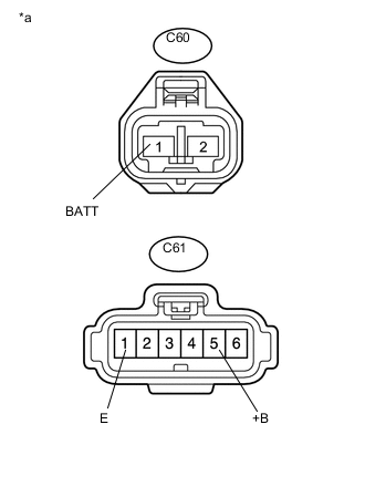
Text in Illustration *a Front view of wire harness connector
(to Air Injection Control Driver)
-
Disconnect the air injection control driver connectors.
-
Measure the resistance according to the value(s) in the table below.
Standard Resistance Tester Connection Condition Specified Condition C61-1 (E) - Body ground Always Below 1 Ω -
Turn the ignition switch to ON.
-
Measure the voltage according to the value(s) in the table below.
Standard Voltage Tester Connection Condition Specified Condition C60-1 (BATT) - Body ground Always 11 to 14 V (near battery voltage) C61-5 (+B) - Body ground Ignition switch ON 11 to 14 V (near battery voltage) -
Reconnect the air injection control driver connectors.
NG
REPAIR OR REPLACE AIR INJECTION CONTROL DRIVER POWER SOURCE CIRCUIT
OK
-
-
CHECK HARNESS AND CONNECTOR (ECM - AIR INJECTION CONTROL DRIVER)
-
Disconnect the ECM connector.
-
Disconnect the air injection control driver connector.
-
Measure the resistance according to the value(s) in the table below.
Standard Resistance Tester Connection Condition Specified Condition C45-54 (AIRP) - C61-4 (SIP) Always Below 1 Ω C61-4 (SIP) - Body ground Always 10 kΩ or higher -
Reconnect the ECM connector.
-
Reconnect the air injection control driver connector.
NG
REPAIR OR REPLACE HARNESS OR CONNECTOR
OK
-
-
CHECK AIR PUMP ASSEMBLY
-
Inspect the air pump assembly Click here.
OK
PERFORM ACTIVE TEST USING GTS Click here
NG
-
-
REPLACE AIR PUMP ASSEMBLY
-
Replace the air pump assembly Click here.
NEXT
-
-
CHECK WHETHER DTC OUTPUT RECURS (DTC P2445)
-
Start the engine and warm it up.
-
Turn the ignition switch off.
-
Connect the GTS to the DLC3.
-
Turn the ignition switch to ON.
-
Turn the GTS on.
-
Clear the DTCs (if stored) Click here.
-
Enter the following menus: Powertrain / Engine and ECT / Utility / Secondary Air Injection Check / Automatic Mode.
-
Start the engine after the GTS initialization is finished.
-
Perform the System Check operation by pressing ENTER (Next).
-
Perform the following to confirm the secondary air injection system pending codes: Press the Exit button.
-
Check for pending DTCs.
OK No pending DTC is output. -
Turn the ignition switch off.
Note
-
When performing the Secondary Air Injection Check operation after the battery cable has been reconnected, wait for 7 minutes with the ignition switch turned to ON or the engine running.
-
Turn the ignition switch off when the Secondary Air Injection Check operation finishes.
-
OK
END
NG
-
-
PERFORM ACTIVE TEST USING GTS
-
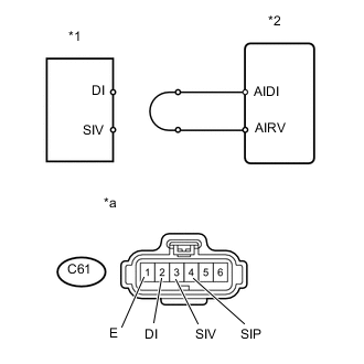
Text in Illustration *1 Air Injection Control Driver *2 ECM *a Front view of wire harness connector
(to Air Injection Control Driver)
Disconnect the air injection control driver connector.
-
Connect terminals DI and SIV of the wire harness connector for the air injection control driver.
-
Connect the GTS to the DLC3.
-
Turn the ignition switch to ON and turn the GTS on.
-
Enter the following menus: Powertrain / Engine and ECT / Utility / Secondary Air Injection Check / Manual Mode / AIR PUMP: ON, ASV 1: OPEN, ASV 2: OPEN.
Tech Tips
When Manual Mode is selected, the GTS initialization (atmospheric pressure measurement) is performed automatically. The initialization takes 10 seconds. After the initialization, AIR PUMP and ASV operation can be selected.
-
Start the engine.
-
Perform the secondary air injection system forced operation while the engine is idling.
-
Measure the voltage between the SIV and E terminals of the ECM connector when the secondary air injection system is ON and OFF.
-
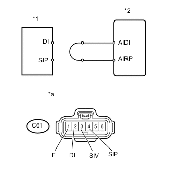
Text in Illustration *1 Air Injection Control Driver *2 ECM *a Front view of wire harness connector
(to Air Injection Control Driver)
Turn the ignition switch off.
Note
-
Performing Secondary Air Injection Check repeatedly may cause damage to the secondary air injection system. If it is necessary to repeat the check, leave an interval of several minutes between System Check operations to prevent the system from overheating.
-
When performing the Secondary Air Injection Check operation after the battery cable has been reconnected, wait for 7 minutes with the ignition switch ON or the engine running.
-
Turn the ignition switch off when the Secondary Air Injection Check operation finishes.
Standard Voltage Tester Connection Condition Specified Condition C61-3 (SIV) - C61-1 (E) AIR PUMP: ON, ASV: OPEN 0.5 to 2 V C61-3 (SIV) - C61-1 (E) AIR PUMP: OFF, ASV: CLOSE 11 to 14 V -
-
Connect terminals DI and SIP of the wire harness connector for the air injection control driver.
-
Connect the GTS to the DLC3.
-
Turn the ignition switch to ON and turn the GTS on.
-
Enter the following menus: Powertrain / Engine and ECT / Utility / Secondary Air Injection Check / Manual Mode / AIR PUMP: ON, ASV 1: OPEN, ASV 2: OPEN.
Tech Tips
When Manual Mode is selected, the GTS initialization (atmospheric pressure measurement) is performed automatically. The initialization takes 10 seconds. After the initialization, AIR PUMP and ASV operation can be selected.
-
Start the engine.
-
Perform the secondary air injection system forced operation while the engine is idling.
-
Measure the voltage between the SIP and E terminals of the ECM connector when the secondary air injection system is ON and OFF.
-
Turn the ignition switch off.
Note
-
Performing Secondary Air Injection Check repeatedly may cause damage to the secondary air injection system. If it is necessary to repeat the check, leave an interval of several minutes between System Check operations to prevent the system from overheating.
-
When performing the Secondary Air Injection Check operation after the battery cable has been reconnected, wait for 7 minutes with the ignition switch ON or the engine running.
-
Turn the ignition switch off when the Secondary Air Injection Check operation finishes.
Standard Voltage Tester Connection Condition Specified Condition C61-4 (SIP) - C61-1 (E) AIR PUMP: ON, ASV: OPEN 0.5 to 2 V C61-4 (SIP) - C61-1 (E) AIR PUMP: OFF, ASV: CLOSE 11 to 14 V -
-
Reconnect the air injection control driver connector.
NG
REPLACE ECM Click here
OK
-
-
REPLACE AIR INJECTION CONTROL DRIVER
-
Replace the air injection control driver Click here.
NEXT
-
-
CHECK WHETHER DTC OUTPUT RECURS (DTC P2445)
-
Start the engine and warm it up.
-
Turn the ignition switch off.
-
Connect the GTS to the DLC3.
-
Turn the ignition switch to ON.
-
Turn the GTS on.
-
Clear the DTCs (if stored) Click here.
-
Enter the following menus: Powertrain / Engine and ECT / Utility / Secondary Air Injection Check / Automatic Mode.
-
Start the engine after the GTS initialization is finished.
-
Perform the System Check operation by pressing ENTER (Next).
-
Perform the following to confirm the secondary air injection system pending codes: Press the Exit button.
-
Check for pending DTCs.
OK No pending DTC is output. -
Turn the ignition switch off.
Note
-
When performing the Secondary Air Injection Check operation after the battery cable has been reconnected, wait for 7 minutes with the ignition switch ON or the engine running.
-
Turn the ignition switch off when the Secondary Air Injection Check operation finishes.
-
OK
END
NG
REPLACE ECM Click here
-