INTAKE MANIFOLD INSTALLATION
PROCEDURE
-
INSTALL THROTTLE BODY WITH MOTOR ASSEMBLY
-
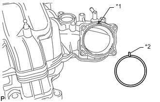
Text in Illustration *1 Groove *2 Protrusion Align the protrusion of a new gasket with the groove of the intake manifold and install the gasket.
-
Install the throttle body with motor assembly with the 4 bolts.
- Torque:
- 10 N*m { 102 kgf*cm, 7 ft.*lbf }
-
-
INSTALL MANIFOLD ABSOLUTE PRESSURE SENSOR
-
INSTALL PURGE VSV
-
Connect the purge line hose to the intake manifold.
-
Install the purge VSV to the intake manifold with the bolt.
- Torque:
- 21 N*m { 214 kgf*cm, 15 ft.*lbf }
-
-
INSTALL VACUUM SWITCHING VALVE ASSEMBLY (for ACIS)
-
Install the vacuum switching valve to the intake manifold with the bolt.
- Torque:
- 9.0 N*m { 92 kgf*cm, 80 in.*lbf }
-
Connect the 2 vacuum hoses to the vacuum switching valve and attach the 3 clamps.
-
-
INSTALL STUD BOLT
Note
If a stud bolt is deformed or its threads are damaged, replace it.
-
Using an E5 "TORX" socket wrench, install the 2 stud bolts to the intake manifold.
- Torque:
- 5.0 N*m { 51 kgf*cm, 44 in.*lbf }
-
-
INSTALL INTAKE FLANGE
-
Install the intake flange with the 2 nuts.
- Torque:
- 10 N*m { 102 kgf*cm, 7 ft.*lbf }
-
-
INSTALL V-BANK COVER PIN
-
Install the V-bank cover pin to the intake manifold.
- Torque:
- 10 N*m { 102 kgf*cm, 7 ft.*lbf }
-
-
INSTALL V-BANK COVER BRACKET
-
Install the V-bank cover bracket with the 2 bolts.
- Torque:
- 10 N*m { 102 kgf*cm, 7 ft.*lbf }
-
-
INSTALL BRACKET
-
Install the 2 brackets with the 2 bolts.
- Torque:
- 8.0 N*m { 82 kgf*cm, 71 in.*lbf }
-
-
INSTALL FUEL TUBE SUB-ASSEMBLY
-
Install the fuel tube to the intake manifold with the bolt.
- Torque:
- 10 N*m { 102 kgf*cm, 7 ft.*lbf }
-
-
INSTALL INTAKE MANIFOLD
-
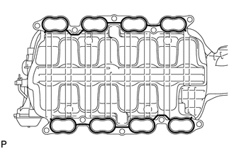
Place 2 new gaskets on the intake manifold.
-
Place the intake manifold on the cylinder head.
-
Install and uniformly tighten the 8 bolts and 2 nuts in several steps.
- Torque:
- 21 N*m { 214 kgf*cm, 15 ft.*lbf }
-
Connect the fuel tube to the No. 2 fuel delivery pipe Click here.
-
Connect the fuel tube to the fuel delivery pipe Click here.
-
Attach the 3 wire harness clamps to the 3 wire harness brackets.
-
Install the bolt.
- Torque:
- 8.0 N*m { 82 kgf*cm, 71 in.*lbf }
-
Connect the purge VSV connector.
-
Connect the purge line hose to the purge VSV.
-
Connect the vacuum switching valve connector (for ACIS).
-
Connect the PCV valve hose.
-
Connect the No. 4 water by-pass hose.
-
Connect the throttle position sensor and throttle control motor connector.
-
w/o Secondary Air Injection System:
-
Install the bracket with the 2 bolts.
- Torque:
- 10 N*m { 102 kgf*cm, 7 ft.*lbf }
-
Attach the clamp and connect the manifold absolute pressure sensor connector.
-
-
-
INSTALL AIR TUBE SUB-ASSEMBLY (w/ Secondary Air Injection System)
-
Install the air tube.
-
Install the bolt.
- Torque:
- 10 N*m { 102 kgf*cm, 7 ft.*lbf }
-
Install the bracket with the 2 bolts.
- Torque:
- 10 N*m { 102 kgf*cm, 7 ft.*lbf }
-
Attach the clamp and connect the manifold absolute pressure sensor connector.
-
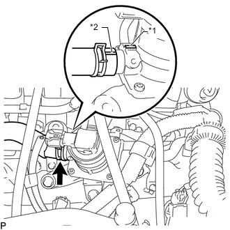
Text in Illustration *1 Projection *2 Paint Mark Align the paint mark with the projection and connect the No. 2 air injection system hose.
Tech Tips
Make sure the direction of the hose clamp is as shown in the illustration.
-
-
INSTALL PCV HOSE ASSEMBLY
-
Install the PCV hose with the bolt.
- Torque:
- 10 N*m { 102 kgf*cm, 7 ft.*lbf }
-
Connect the PCV hose to the PCV pipe of the cylinder head cover LH and RH.
-
-
INSTALL EGR VALVE BRACKET
-
Install the EGR valve bracket with the 3 bolts.
- Torque:
- 21 N*m { 214 kgf*cm, 15 ft.*lbf }
-
Attach the 2 wire harness clamps and PCV hose clamp.
-
-
INSTALL NO. 5 WATER BY-PASS PIPE
-
Install the No. 5 water by-pass pipe with the 2 bolts and connect the 2 water by-pass hoses.
- Torque:
- 21 N*m { 214 kgf*cm, 15 ft.*lbf }
-
-
ADD ENGINE COOLANT
-
INSTALL NO. 1 ENGINE UNDER COVER SUB-ASSEMBLY
-
INSTALL FRONT FENDER SPLASH SHIELD SUB-ASSEMBLY LH
-
INSTALL FRONT FENDER SPLASH SHIELD SUB-ASSEMBLY RH
-
INSTALL AIR CLEANER CAP AND HOSE
-
INSTALL V-BANK COVER SUB-ASSEMBLY
-
CONNECT CABLE TO NEGATIVE BATTERY TERMINAL
Note
When disconnecting the cable, some systems need to be initialized after the cable is reconnected Click here.
-
INSPECT FOR FUEL LEAK
-
PERFORM INITIALIZATION