FUEL INJECTOR(w/o DPF) INSTALLATION
CAUTION / NOTICE / HINT
Note
When replacing an injector (including interchanging injectors between cylinders) or common rail, replace the corresponding injection pipes with new ones.
PROCEDURE
-
INSTALL FUEL INJECTOR LH
Note
Be sure to install the injector, holder clamp and bolt to their original positions.
-
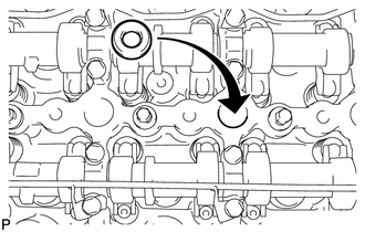
Install 4 new injection nozzle seats to the cylinder head.
-
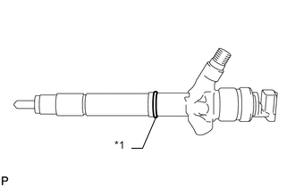
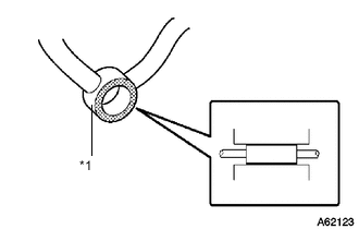
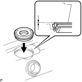
Text in Illustration *1 New O-Ring Apply a light coat of clean engine oil to 4 new O-rings.
-
Install the O-rings to each injector as shown in the illustration.
-
Insert the 4 injectors into the cylinder head.
Note
-
Insert the injector until it touches the nozzle seat surface.
-
After installing the injector to the cylinder head, the O-ring may prevent the injector from fully seating. If so, pull out the injector and reinstall it.
-
Always return an injector to the same place it was removed from.
-
-
For an injector that has been replaced with a new injector, register the injector compensation code.
-
Temporarily install 4 new washers and the 4 nozzle clamps with the 4 clamp bolts.
Note
-
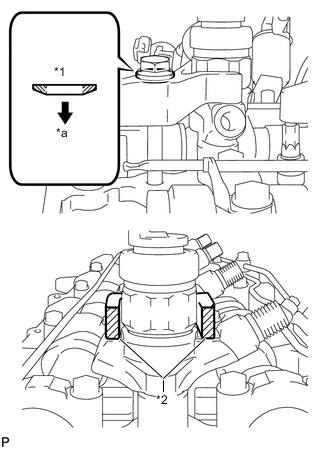
The fork portion of the nozzle holder clamp must be set on the injector.
-
Before tightening the bolts, check that the nozzle holder clamp is set properly.
-
To tighten the clamp bolts, first tighten them by hand until they cannot be turned further. Then, tighten the bolts to the specified torque in a later step.
-
When tightening the bolts, be careful not to tilt the bolt and clamp.
-
Do not reuse the washer.
Text in Illustration *1 Washer *2 Nozzle Holder Clamp *a Downward -
-
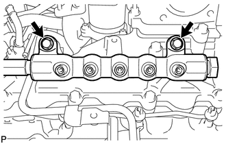
Temporarily install the common rail LH with the 2 bolts.
-
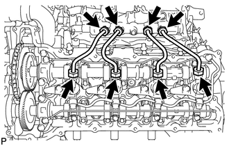
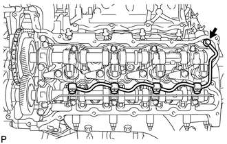
Temporarily install 4 new injection pipes to the common rail and injector.
-
Text in Illustration *1 Nozzle Leakage Pipe Check the nozzle leakage pipe. Check that there are no scratches or dents on the 5 union seal surfaces. If scratches or dents are present, replace the nozzle leakage pipe.
-
Set the leakage pipe and 5 new gaskets in place.
-
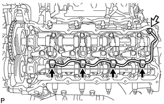
Temporarily install the leakage pipe with the 4 hollow screws and union bolt.
Text in Illustration 
Union Bolt Tech Tips
To position the injectors, loosely tighten the 4 hollow screws and union bolt.
-
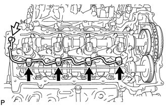
Tighten the 4 holder clamp bolts.
- Torque:
- 25 N*m { 255 kgf*cm, 18 ft.*lbf }
-
Remove the 4 injection pipes.
-
Remove the 2 bolts and common rail LH.
-
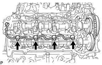
Tighten the 4 hollow screws.
- Torque:
- 18 N*m { 184 kgf*cm, 13 ft.*lbf }
Note
If a hollow screw is accidentally tightened beyond the torque specification, it must be replaced together with the nozzle leakage pipe.
-
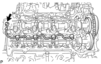
Tighten the union bolt.
- Torque:
- 21 N*m { 214 kgf*cm, 15 ft.*lbf }
Note
If the union bolt is accidentally tightened beyond the torque specification, it must be replaced together with the nozzle leakage pipe.
-
-
INSTALL FUEL INJECTOR RH
Note
Be sure to install the injector, holder clamp and bolt to their original positions.
-
Install 4 new injection nozzle seats to the cylinder head.
-
Text in Illustration *1 New O-Ring Apply a light coat of clean engine oil to 4 new O-rings.
-
Install the O-rings to each injector as shown in the illustration.
-
Insert the 4 injectors into the cylinder head.
Note
-
Insert the injector until it touches the nozzle seat surface.
-
After installing the injector to the cylinder head, the O-ring may prevent the injector from fully seating. If so, pull out the injector and reinstall it.
-
Always return an injector to the same place it was removed from.
-
-
For an injector that has been replaced with a new injector, register the injector compensation code.
-
Temporarily install 4 new washers and the 4 nozzle clamps with the 4 clamp bolts.
Note
-
The fork portion of the nozzle holder clamp must be set on the injector.
-
Before tightening the bolts, check that the nozzle holder clamp is set properly.
-
To tighten the clamp bolts, first tighten them by hand until they cannot be turned further. Then, tighten the bolts to the specified torque in a later step.
-
When tightening the bolts, be careful not to tilt the bolt and clamp.
-
Do not reuse the washer.
Text in Illustration *1 Washer *2 Nozzle Holder Clamp *a Downward -
-
Temporarily install 4 new injection pipes to the common rail and injector.
-
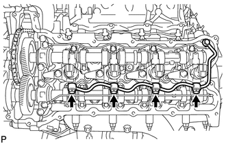
Text in Illustration *1 Nozzle Leakage Pipe Check the nozzle leakage pipe. Check that there are no scratches or dents on the 5 union seal surfaces. If scratches or dents are present, replace the nozzle leakage pipe.
-
Set the leakage pipe and 5 new gaskets in place.
-
Temporarily install the leakage pipe with the 4 hollow screws and union bolt.
Text in Illustration Union Bolt Tech Tips
To position the injectors, loosely tighten the 4 hollow screws and union bolt.
-
Tighten the 4 holder clamp bolts.
- Torque:
- 25 N*m { 255 kgf*cm, 18 ft.*lbf }
-
Remove the 4 injection pipes.
-
Tighten the 4 hollow screws.
- Torque:
- 18 N*m { 184 kgf*cm, 13 ft.*lbf }
Note
If a hollow screw is accidentally tightened beyond the torque specification, it must be replaced together with the nozzle leakage pipe.
-
Tighten the union bolt.
- Torque:
- 21 N*m { 214 kgf*cm, 15 ft.*lbf }
Note
If the union bolt is accidentally tightened beyond the torque specification, it must be replaced together with the nozzle leakage pipe.
-
-
INSTALL NOZZLE HOLDER GASKET RH
-
Text in Illustration *1 Nozzle Holder Gasket Press 4 new nozzle holder gaskets into the cylinder head cover RH.
Note
After installing the nozzle holder gasket, check that it does not protrude from the cylinder head cover.
-
-
INSTALL CYLINDER HEAD COVER SUB-ASSEMBLY RH
-
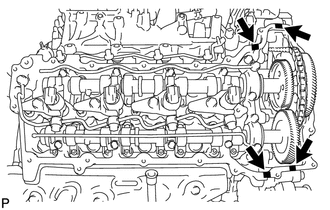
Apply seal packing as shown in the illustration.
Seal packing Toyota Genuine Seal Packing Black, Three Bond 1207B or equivalent Text in Illustration 
Seal Packing Note
-
Remove any oil from the contact surface.
-
Install the cylinder head cover within 3 minutes and tighten the bolts within 15 minutes after applying seal packing.
-
Do not start the engine for at least 2 hours after the installation.
-
-
Install a new gasket to the cylinder head cover.
Note
Remove any oil from the contact surface.
-
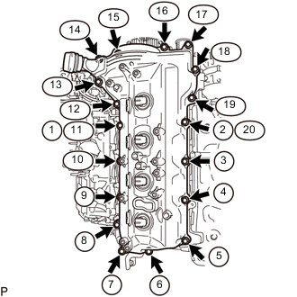
Temporarily install the cylinder head cover with the 18 bolts. Tighten the 18 bolts in the order shown in the illustration.
- Torque:
- 10 N*m { 102 kgf*cm, 7 ft.*lbf }
Tech Tips
After tightening the bolts, check that the bolts at step 11 and 20 are tightened to the specified torque.
-
-
INSTALL NOZZLE HOLDER SEAL RH
-
Press 4 new holder seals into the cylinder head cover RH.
-
-
INSTALL CYLINDER HEAD COVER SILENCER RH (w/ Intercooler)
-
Install the cylinder head cover silencer with the 3 bolts.
- Torque:
- 5.0 N*m { 51 kgf*cm, 44 in.*lbf }
-
-
INSTALL NO. 2 VENTILATION HOSE
-
INSTALL NOZZLE HOLDER GASKET LH
-
Text in Illustration *1 Nozzle Holder Gasket Press 4 new nozzle holder gaskets into the cylinder head cover LH.
Note
After installing the nozzle holder gasket, check that it does not protrude from the cylinder head cover.
-
-
INSTALL CYLINDER HEAD COVER SUB-ASSEMBLY LH
-
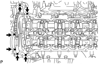
Apply seal packing as shown in the illustration.
Seal packing Toyota Genuine Seal Packing Black, Three Bond 1207B or equivalent Text in Illustration Seal Packing Note
-
Remove any oil from the contact surface.
-
Install the cylinder head cover within 3 minutes and tighten the bolts within 15 minutes after applying seal packing.
-
Do not start the engine for at least 2 hours after the installation.
-
-
Install a new gasket to the cylinder head cover.
Note
Remove any oil from the contact surface.
-
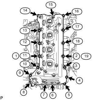
Temporarily install the cylinder head cover with the 17 bolts. Tighten the 17 bolts in the order shown in the illustration.
- Torque:
- 10 N*m { 102 kgf*cm, 7 ft.*lbf }
Tech Tips
After tightening the bolts, check that the bolts at step 11 and 19 are tightened to the specified torque.
-
-
INSTALL OIL SEPARATOR ASSEMBLY
-
Install a new gasket to the oil separator.
Note
Remove any oil from the contact surface.
-
Install the oil separator with the 3 bolts.
- Torque:
- 10 N*m { 102 kgf*cm, 7 ft.*lbf }
-
-
INSTALL NOZZLE HOLDER SEAL LH
-
Press 4 new holder seals into the cylinder head cover LH.
-
-
INSTALL CYLINDER HEAD COVER SILENCER LH (w/ Intercooler)
-
Install the cylinder head cover silencer with the 3 bolts.
- Torque:
- 5.0 N*m { 51 kgf*cm, 44 in.*lbf }
-
-
INSTALL NO. 3 VENTILATION HOSE
-
INSTALL NO. 1 VACUUM TRANSMITTING PIPE SUB-ASSEMBLY
-
Install the vacuum transmitting pipe with the 3 bolts.
- Torque:
- 6.0 N*m { 61 kgf*cm, 53 in.*lbf }
-
w/ Intercooler:
Connect the 2 vacuum hoses.
-
-
INSTALL NO. 1 VACUUM SWITCHING VALVE ASSEMBLY (for Engine Mounting)
-
Install the vacuum switching valve with the bolt.
- Torque:
- 6.0 N*m { 61 kgf*cm, 53 in.*lbf }
-
Connect the 2 vacuum hoses.
-
-
INSTALL NO. 2 ENGINE WIRE
-
INSTALL INJECTION PIPE RH
-
INSTALL FUEL FILTER TO INJECTION PUMP FUEL PIPE SUB-ASSEMBLY
-
INSTALL COMMON RAIL ASSEMBLY LH
-
INSTALL INJECTION PIPE LH
-
INSTALL NO. 6 INJECTION PIPE SUB-ASSEMBLY
-
INSTALL NO. 2 FUEL PIPE SUB-ASSEMBLY
-
CONNECT ENGINE WIRE
-
INSTALL NO. 4 WATER BY-PASS PIPE
-
INSTALL NO. 3 WATER BY-PASS PIPE (w/o Viscous Heater)
-
CONNECT FUEL HOSE
-
INSTALL NO. 1 AIR CLEANER PIPE SUB-ASSEMBLY
-
INSTALL HEATER WATER PIPE SUB-ASSEMBLY (w/ Viscous Heater)
-
INSTALL NO. 2 AIR CLEANER PIPE SUB-ASSEMBLY
-
INSTALL NO. 4 AIR TUBE
-
INSTALL NO. 2 AIR HOSE
-
INSTALL NO. 3 AIR TUBE
-
INSTALL INTAKE AIR CONNECTOR
-
TEMPORARILY INSTALL NO. 1 AIR CLEANER HOSE
-
INSTALL AIR CLEANER CAP SUB-ASSEMBLY
-
INSTALL DIESEL THROTTLE BODY ASSEMBLY LH
-
INSTALL NO. 3 INTERCOOLER SUPPORT BRACKET
-
INSTALL NO. 1 GAS FILTER
-
INSTALL TUBE CONNECTOR TO FLEXIBLE HOSE TUBE (for Manual Transmission)
-
INSTALL AIR TUBE SUB-ASSEMBLY LH
-
INSTALL CLUTCH HOSE (for Manual Transmission)
-
INSTALL DIESEL THROTTLE BODY ASSEMBLY RH
-
INSTALL AIR TUBE SUB-ASSEMBLY RH
-
INSTALL NO. 2 ENGINE OIL LEVEL DIPSTICK GUIDE
-
CONNECT WATER HOSE SUB-ASSEMBLY
-
INSTALL NO. 2 COOL AIR INLET (w/o Intercooler)
-
INSTALL NO. 1 COOL AIR INLET (w/o Intercooler)
-
INSTALL INTERCOOLER ASSEMBLY (w/ Intercooler)
-
BLEED CLUTCH LINE (for Manual Transmission)
-
INSPECT FOR CLUTCH FLUID LEAK (for Manual Transmission)
-
CONNECT CABLE TO NEGATIVE BATTERY TERMINAL
Note
When disconnecting the cable, some systems need to be initialized after the cable is reconnected Click here.
-
Connect the cables to the negative (-) main battery and sub-battery terminals.
-
-
REGISTER INJECTOR COMPENSATION CODE
-
ADD ENGINE COOLANT
-
INSPECT FOR COOLANT LEAK
-
INSPECT FOR FUEL LEAK
-
INSPECT FOR OIL LEAK
-
INSTALL UPPER RADIATOR SUPPORT SEAL
-
INSTALL NO. 1 ENGINE UNDER COVER SUB-ASSEMBLY
-
INSTALL FRONT FENDER SPLASH SHIELD SUB-ASSEMBLY RH
-
INSTALL FRONT FENDER SPLASH SHIELD SUB-ASSEMBLY LH