FUEL INJECTOR(w/o DPF) REMOVAL
CAUTION / NOTICE / HINT
Note
When replacing an injector (including interchanging injectors between cylinders) or common rail, replace the corresponding injection pipes with new ones.
PROCEDURE
-
PRECAUTION
Note
After turning the ignition switch off, waiting time may be required before disconnecting the cable from the battery terminal. Therefore, make sure to read the disconnecting the cable from the battery terminal notice before proceeding with work Click here.
-
DISCONNECT CABLE FROM NEGATIVE BATTERY TERMINAL
Note
When disconnecting the cable, some systems need to be initialized after the cable is reconnected Click here.
-
Disconnect the cables from the negative (-) main battery and sub-battery terminals.
-
-
REMOVE FRONT FENDER SPLASH SHIELD SUB-ASSEMBLY LH
-
REMOVE FRONT FENDER SPLASH SHIELD SUB-ASSEMBLY RH
-
REMOVE NO. 1 ENGINE UNDER COVER SUB-ASSEMBLY
-
REMOVE UPPER RADIATOR SUPPORT SEAL
-
DRAIN ENGINE COOLANT
-
REMOVE INTERCOOLER ASSEMBLY (w/ Intercooler)
-
REMOVE NO. 1 COOL AIR INLET (w/o Intercooler)
-
REMOVE NO. 2 COOL AIR INLET (w/o Intercooler)
-
DISCONNECT WATER HOSE SUB-ASSEMBLY
-
REMOVE NO. 2 ENGINE OIL LEVEL DIPSTICK GUIDE
-
REMOVE AIR TUBE SUB-ASSEMBLY RH
-
REMOVE DIESEL THROTTLE BODY ASSEMBLY RH
-
DRAIN CLUTCH FLUID (for Manual Transmission)
-
REMOVE CLUTCH HOSE (for Manual Transmission)
-
REMOVE AIR TUBE SUB-ASSEMBLY LH
-
REMOVE TUBE CONNECTOR TO FLEXIBLE HOSE TUBE (for Manual Transmission)
-
REMOVE NO. 1 GAS FILTER
-
REMOVE NO. 3 INTERCOOLER SUPPORT BRACKET
-
REMOVE DIESEL THROTTLE BODY ASSEMBLY LH
-
REMOVE AIR CLEANER CAP SUB-ASSEMBLY
-
REMOVE NO. 1 AIR CLEANER HOSE
-
REMOVE INTAKE AIR CONNECTOR
-
REMOVE NO. 3 AIR TUBE
-
REMOVE NO. 2 AIR HOSE
-
REMOVE NO. 4 AIR TUBE
-
REMOVE NO. 2 AIR CLEANER PIPE SUB-ASSEMBLY
-
REMOVE HEATER WATER PIPE SUB-ASSEMBLY (w/ Viscous Heater)
-
REMOVE NO. 1 AIR CLEANER PIPE SUB-ASSEMBLY
-
DISCONNECT FUEL HOSE
-
REMOVE NO. 3 WATER BY-PASS PIPE (w/o Viscous Heater)
-
REMOVE NO. 4 WATER BY-PASS PIPE
-
DISCONNECT ENGINE WIRE
-
REMOVE NO. 2 FUEL PIPE SUB-ASSEMBLY
-
REMOVE NO. 6 INJECTION PIPE SUB-ASSEMBLY
-
REMOVE INJECTION PIPE LH
-
REMOVE COMMON RAIL ASSEMBLY LH
-
REMOVE FUEL FILTER TO INJECTION PUMP FUEL PIPE SUB-ASSEMBLY
-
REMOVE INJECTION PIPE RH
-
DISCONNECT NO. 2 ENGINE WIRE
-
REMOVE NO. 1 VACUUM SWITCHING VALVE ASSEMBLY (for Engine Mounting)
-
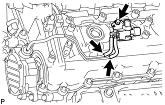
Disconnect the 2 vacuum hoses.
-
Remove the bolt and vacuum switching valve.
-
-
REMOVE NO. 1 VACUUM TRANSMITTING PIPE SUB-ASSEMBLY
-
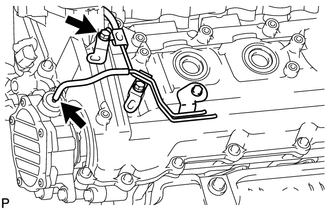
w/ Intercooler:
Disconnect the 2 vacuum hoses.
-
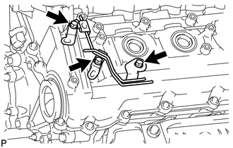
Remove the 3 bolts and vacuum transmitting pipe.
-
-
REMOVE NO. 3 VENTILATION HOSE
-
REMOVE CYLINDER HEAD COVER SILENCER LH (w/ Intercooler)
-
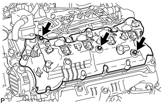
Remove the 3 bolts and cylinder head cover silencer.
-
-
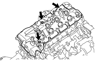
REMOVE NOZZLE HOLDER SEAL LH
-
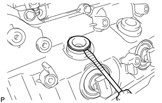
Using a small screwdriver, remove the 4 holder seals by prying the portion between each holder seal and the cutout part of the cylinder head cover.
Tech Tips
Tape the screwdriver tip before use.
-
-
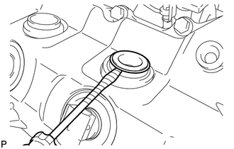
REMOVE OIL SEPARATOR ASSEMBLY
-
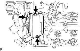
Remove the 3 bolts, oil separator and gasket.
-
-
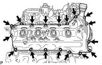
REMOVE CYLINDER HEAD COVER SUB-ASSEMBLY LH
-
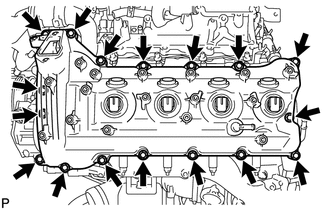
Remove the 17 bolts, cylinder head cover and gasket.
-
-
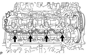
REMOVE NOZZLE HOLDER GASKET LH
-
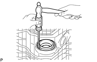
Using a small screwdriver and hammer, remove the 4 nozzle holder gaskets.
Tech Tips
Tape the screwdriver tip before use.
-
-
REMOVE NO. 2 VENTILATION HOSE
-
REMOVE CYLINDER HEAD COVER SILENCER RH (w/ Intercooler)
-
Remove the 3 bolts and cylinder head cover silencer.
-
-
REMOVE NOZZLE HOLDER SEAL RH
-
Using a small screwdriver, remove the 4 holder seals by prying the portion between each holder seal and the cutout part of the cylinder head cover.
Tech Tips
Tape the screwdriver tip before use.
-
-
REMOVE CYLINDER HEAD COVER SUB-ASSEMBLY RH
-
Remove the 18 bolts, cylinder head cover and gasket.
-
-
REMOVE NOZZLE HOLDER GASKET RH
-
Using a small screwdriver and hammer, remove the 4 nozzle holder gaskets.
Tech Tips
Tape the screwdriver tip before use.
-
-
REMOVE FUEL INJECTOR RH
-
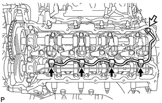
Remove the union bolt, 4 hollow screws, 5 gaskets and nozzle leakage pipe.
Text in Illustration 
Union Bolt Note
-
When removing the nozzle leakage pipe, place a cushion under the pipe.
-
Be careful not to deform or scratch the union seal surface.
-
After removing the nozzle leakage pipe, put it in a plastic bag to prevent foreign matter from contaminating its injector inlet.
-
-
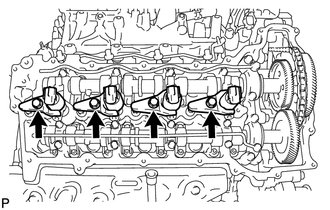
Remove the 4 bolts, 4 washers, 4 nozzle holder clamps and 4 injectors.
Tech Tips
Arrange the injectors, holder clamps, washers and bolts in the correct order.
-
Remove the O-ring from each injector.
-
Remove the 4 injection nozzle seats from the cylinder head.
-
-
REMOVE FUEL INJECTOR LH
-
Remove the union bolt, 4 hollow screws, 5 gaskets and No. 2 nozzle leakage pipe.
Text in Illustration Union Bolt Note
-
When removing the nozzle leakage pipe, place a cushion under the pipe.
-
Be careful not to deform or scratch the union seal surface.
-
After removing the nozzle leakage pipe, put it in a plastic bag to prevent foreign matter from contaminating its injector inlet.
-
-
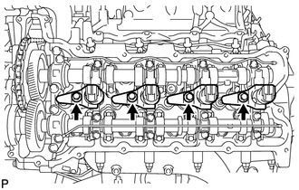
Remove the 4 bolts, 4 washers, 4 nozzle holder clamps and 4 injectors.
Tech Tips
Arrange the injectors, holder clamps, washers and bolts in the correct order.
-
Remove the O-ring from each injector.
-
Remove the 4 injection nozzle seats from the cylinder head.
-