FUEL INJECTOR(w/ DPF) INSTALLATION
CAUTION / NOTICE / HINT
Note
-
When replacing an injector (including interchanging injectors between cylinders) or common rail, replace the corresponding injection pipes with new ones.
-
When fuel lines are disconnected, air may enter the fuel lines, leading to engine starting trouble. Therefore, perform forced regeneration and bleed the air from the fuel lines Click here.
PROCEDURE
-
INSTALL FUEL INJECTOR LH
Note
-
Be sure to install the fuel injector, holder clamp and bolt to their original positions.
-
Before installing the fuel injector, check for carbon, foreign matter, etc. on the seal surfaces of the cylinder head sub-assembly and fuel injector. If there is foreign matter, remove it before installing the fuel injector.
-
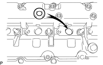
Install 4 new injection nozzle seats to the cylinder head sub-assembly.
-
Text in Illustration *1 Fuel Injector Seal Install 4 new fuel injector seals to each fuel injector as shown in the illustration.
-
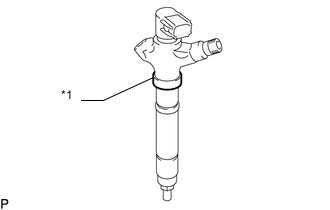
Apply a light coat of clean engine oil to 4 new O-rings.
-
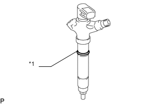
Text in Illustration *1 O-Ring Install the O-rings to each fuel injector as shown in the illustration.
-
Insert the 4 injectors into the cylinder head sub-assembly.
Note
-
Insert the fuel injector until it touches the nozzle seat surface.
-
After installing the fuel injector to the cylinder head sub-assembly, the O-ring may prevent the fuel injector from fully seating. If so, pull out the fuel injector and reinstall it.
-
Always return an fuel injector to the same place it was removed from.
-
-
For an fuel injector that has been replaced with a new fuel injector, register the injector compensation code Click here.
-
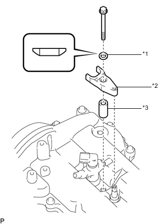
Temporarily install 4 new washers, 4 nozzle holder clamps and 4 new nozzle holder seals with the 4 clamp bolts.
Text in Illustration *1 Washer *2 Nozzle Holder Clamp *3 Nozzle Holder Seal Note
-
The fork portion of the nozzle holder clamp must be set on the fuel injector.
-
Before tightening the bolts, check that the nozzle holder clamp is set properly.
-
To tighten the clamp bolts, first tighten them by hand until they cannot be turned further. Then, tighten the bolts to the specified torque in a later step.
-
When tightening the bolts, be careful not to tilt the bolt and clamp.
-
Do not reuse the washer.
Text in Illustration *1 Nozzle Holder Clamp -
-
Temporarily install the common rail LH with the 2 bolts.
-
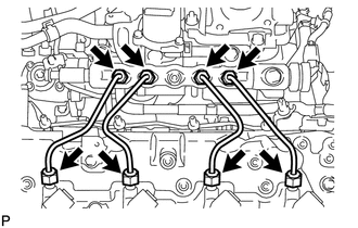
Temporarily install 4 new injection pipes to the common rail and fuel injector.
-
Check the nozzle leakage pipe. Check there are no scratches or dents on the union seal surfaces. If scratches or dents are present, replace the nozzle leakage pipe.
-
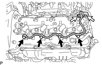
Temporarily install the No. 2 leakage pipe and 4 new gaskets with the 4 injector hollow screws and 2 bolts.
Tech Tips
To position the fuel injectors, loosely tighten the 4 hollow screws and 2 bolts.
Text in Illustration 
Injector Hollow Screw 
Bolt -
Tighten the 4 holder clamp bolts.
- Torque:
- 25 N*m { 255 kgf*cm, 18 ft.*lbf }
-
Remove the 4 injection pipes.
-
Remove the 2 bolts and common rail LH.
-
-
INSTALL NO. 2 NOZZLE LEAKAGE PIPE
-
Tighten the 4 injector hollow screws and 2 bolts.
- Torque:
- for injector hollow screw
- 18 N*m { 184 kgf*cm, 13 ft.*lbf }
- for bolt
- 10 N*m { 102 kgf*cm, 7 ft.*lbf }
-
-
INSTALL FUEL INJECTOR RH
Note
-
Be sure to install the fuel injector, holder clamp and bolt to their original positions.
-
Before installing the fuel injector, check for carbon, foreign matter, etc. on the seal surfaces of the cylinder head sub-assembly and fuel injector. If there is foreign matter, remove it before installing the fuel injector.
-
Install 4 new injection nozzle seats to the cylinder head sub-assembly.
-
Text in Illustration *1 Fuel Injector Seal Install 4 new fuel injector seals to each fuel injector as shown in the illustration.
-
Apply a light coat of clean engine oil to 4 new O-rings.
-
Text in Illustration *1 O-Ring Install the O-rings to each fuel injector as shown in the illustration.
-
Insert the 4 fuel injectors into the cylinder head sub-assembly.
Note
-
Insert the fuel injector until it touches the nozzle seat surface.
-
After installing the fuel injector to the cylinder head sub-assembly, the O-ring may prevent the fuel injector from fully seating. If so, pull out the fuel injector and reinstall it.
-
Always return an fuel injector to the same place it was removed from.
-
-
For an fuel injector that has been replaced with a new injector, register the injector compensation code Click here.
-
Temporarily install 4 new washers, 4 nozzle holder clamps and 4 new nozzle holder seals with the 4 clamp bolts.
Text in Illustration *1 Washer *2 Nozzle Holder Clamp *3 Nozzle Holder Seal Note
-
The fork portion of the nozzle holder clamp must be set on the fuel injector.
-
Before tightening the bolts, check that the nozzle holder clamp is set properly.
-
To tighten the clamp bolts, first tighten them by hand until they cannot be turned further. Then, tighten the bolts to the specified torque in a later step.
-
When tightening the bolts, be careful not to tilt the bolt and clamp.
-
Do not reuse the washer.
Text in Illustration *1 Nozzle Holder Clamp -
-
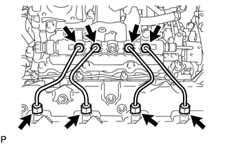
Temporarily install 4 new injection pipes to the common rail and fuel injector.
-
Check the nozzle leakage pipe. Check that there are no scratches or dents on the union seal surfaces. If scratches or dents are present, replace the nozzle leakage pipe.
-
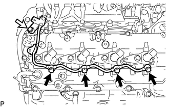
Temporarily install the No. 1 leakage pipe and 4 new gaskets with the 4 injector hollow screws and union bolt.
Tech Tips
To position the injectors, loosely tighten the 4 hollow screws and union bolt.
Text in Illustration Injector Hollow Screw Union Bolt -
Tighten the 4 holder clamp bolts.
- Torque:
- 25 N*m { 255 kgf*cm, 18 ft.*lbf }
-
Remove the 4 injection pipes.
-
-
INSTALL NO. 1 NOZZLE LEAKAGE PIPE
-
Tighten the union bolt and 4 injector hollow screws.
- Torque:
- for union bolt
- 21 N*m { 214 kgf*cm, 15 ft.*lbf }
- for injector hollow screw
- 18 N*m { 184 kgf*cm, 13 ft.*lbf }
-
Install the fuel tube and No. 1 nozzle leakage pipe with the check valve and new gasket.
- Torque:
- 32 N*m { 321 kgf*cm, 23 ft.*lbf }
-
-
INSTALL NO. 3 NOZZLE LEAKAGE PIPE
-
CONNECT CONNECTING WIRE
-
INSTALL CYLINDER HEAD COVER INSULATOR RH
-
INSTALL NO. 2 ENGINE WIRE
-
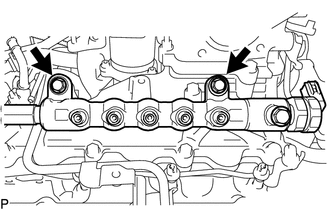
INSTALL INJECTION PIPE RH
-
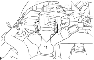
INSTALL NO. 1 FUEL INJECTOR PROTECTOR
-
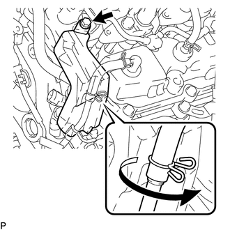
Install the No. 1 fuel injector protector with the bolt.
- Torque:
- 10 N*m { 102 kgf*cm, 7 ft.*lbf }
Tech Tips
Press the ventilation hose clip against the No. 1 fuel injector protector as shown in the illustration.
-
-
INSTALL CYLINDER HEAD COVER SILENCER RH
-
Install the cylinder head cover silencer with the 4 bolts.
- Torque:
- 5.0 N*m { 51 kgf*cm, 44 in.*lbf }
-
-
INSTALL FUEL FILTER TO INJECTION PUMP FUEL PIPE SUB-ASSEMBLY
-
INSTALL COMMON RAIL ASSEMBLY LH
-
INSTALL CYLINDER HEAD COVER INSULATOR LH
-
INSTALL INJECTION PIPE LH
-
INSTALL NO. 2 FUEL INJECTOR PROTECTOR
-
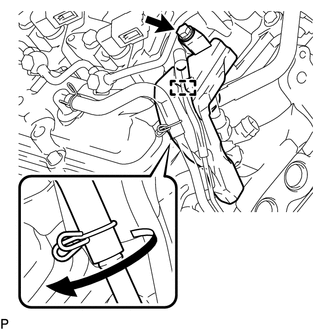
Install the No. 2 fuel injector protector with the bolt.
- Torque:
- 10 N*m { 102 kgf*cm, 7 ft.*lbf }
Tech Tips
Press the ventilation hose clip against the No. 2 fuel injector protector as shown in the illustration.
-
Attach the hose clamp.
-
-
INSTALL NO. 4 NOZZLE LEAKAGE PIPE
-
INSTALL CYLINDER HEAD COVER SILENCER LH
-
Install the cylinder head cover silencer with the 4 bolts.
- Torque:
- 5.0 N*m { 51 kgf*cm, 44 in.*lbf }
-
-
INSTALL NO. 1 VACUUM TRANSMITTING PIPE SUB-ASSEMBLY
-
Install the vacuum transmitting pipe with the 3 bolts.
- Torque:
- 6.0 N*m { 61 kgf*cm, 53 in.*lbf }
-
Connect the 2 vacuum hoses.
-
-
INSTALL NO. 1 VACUUM SWITCHING VALVE ASSEMBLY (for Engine Mounting)
-
Install the vacuum switching valve with the bolt.
- Torque:
- 6.0 N*m { 61 kgf*cm, 53 in.*lbf }
-
Connect the 2 vacuum hoses.
-
-
INSTALL NO. 6 INJECTION PIPE SUB-ASSEMBLY
-
CONNECT ENGINE WIRE
-
INSTALL NO. 4 WATER BY-PASS PIPE
-
INSTALL NO. 3 WATER BY-PASS PIPE (w/o Viscous Heater)
-
CONNECT FUEL HOSE
-
INSTALL NO. 1 AIR CLEANER PIPE SUB-ASSEMBLY
-
INSTALL HEATER WATER PIPE SUB-ASSEMBLY (w/ Viscous Heater)
-
INSTALL NO. 2 AIR CLEANER PIPE SUB-ASSEMBLY
-
INSTALL NO. 4 AIR TUBE
-
INSTALL NO. 2 AIR HOSE
-
INSTALL NO. 3 AIR TUBE
-
INSTALL NO. 1 AIR HOSE
-
INSTALL INTAKE AIR CONNECTOR
-
TEMPORARILY INSTALL NO. 1 AIR CLEANER HOSE
-
INSTALL AIR CLEANER CAP SUB-ASSEMBLY
-
INSTALL DIESEL THROTTLE BODY ASSEMBLY LH
-
INSTALL NO. 3 INTERCOOLER SUPPORT BRACKET
-
INSTALL NO. 1 GAS FILTER
-
INSTALL AIR TUBE SUB-ASSEMBLY LH
-
INSTALL DIESEL THROTTLE BODY ASSEMBLY RH
-
INSTALL AIR TUBE SUB-ASSEMBLY RH
-
INSTALL NO. 2 ENGINE OIL LEVEL DIPSTICK GUIDE
-
CONNECT WATER HOSE SUB-ASSEMBLY
-
INSTALL INTERCOOLER ASSEMBLY
-
CONNECT CABLE TO NEGATIVE BATTERY TERMINAL
Note
When disconnecting the cable, some systems need to be initialized after the cable is reconnected Click here.
-
Connect the cables to the negative (-) main battery and sub-battery terminals.
-
-
REGISTER INJECTOR COMPENSATION CODE
-
ADD ENGINE COOLANT
-
INSPECT FOR COOLANT LEAK
-
INSPECT FOR FUEL LEAK
-
INSPECT FOR OIL LEAK
-
INSTALL UPPER RADIATOR SUPPORT SEAL
-
INSTALL NO. 1 ENGINE UNDER COVER SUB-ASSEMBLY
-
INSTALL FRONT FENDER SPLASH SHIELD SUB-ASSEMBLY RH
-
INSTALL FRONT FENDER SPLASH SHIELD SUB-ASSEMBLY LH