LOWER INSTRUMENT PANEL REMOVAL
PROCEDURE
-
PRECAUTION
-
REMOVE UPPER INSTRUMENT PANEL ASSEMBLY
-
REMOVE FRONT DOOR SCUFF PLATE LH
-
REMOVE COWL SIDE TRIM SUB-ASSEMBLY LH
-
REMOVE STEERING COLUMN COVER
-
REMOVE NO. 1 INSTRUMENT PANEL UNDER COVER SUB-ASSEMBLY (for LHD)
-
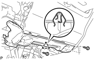
Remove the 2 screws <E>.
-
Disengage the clip.
-
Disengage the clamp.
-
Disconnect each connector and remove the No. 1 instrument panel under cover sub-assembly.
-
-
REMOVE NO. 1 INSTRUMENT PANEL UNDER COVER SUB-ASSEMBLY (for RHD)
-
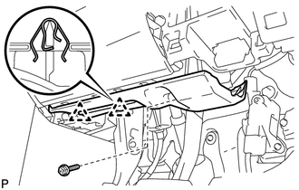
Remove the screw <E>.
-
Disengage the 2 clips.
-
Disengage the clamp.
-
Disconnect each connector and remove the No. 1 instrument panel under cover sub-assembly.
-
-
REMOVE LOWER NO. 1 INSTRUMENT PANEL AIRBAG ASSEMBLY
-
REMOVE LOWER CENTER INSTRUMENT PANEL FINISH PANEL
-
REMOVE AIR CONDITIONING CONTROL ASSEMBLY
-
REMOVE UPPER NO. 2 CONSOLE PANEL GARNISH
-
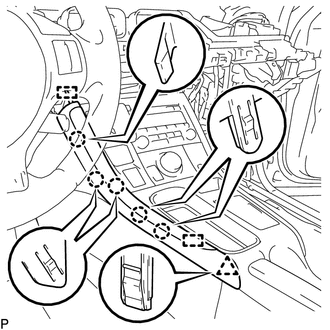
Disengage the 5 claws, clip and 2 guides, and remove the upper No. 2 console panel garnish.
-
-
REMOVE UPPER NO. 1 CONSOLE PANEL GARNISH
-
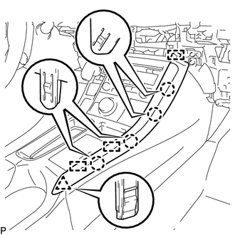
Disengage the 4 claws, clip and 3 guides, and remove the upper No. 1 console panel garnish.
-
-
REMOVE UPPER CONSOLE PANEL SUB-ASSEMBLY
-
Open the console compartment door.
-
Using a moulding remover, disengage the 9 claws of the vehicle rear side.
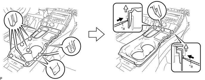
Text in Illustration *a Protective Tape - - -
Using a screwdriver with its tip wrapped with protective tape, disengage the 3 claws of the vehicle front side as shown in the illustration.
-
Disengage the clamp.
-
Disconnect each connector and remove the upper console panel sub-assembly.
-
-
REMOVE REAR CONSOLE BOX POCKET
-
REMOVE CONSOLE BOX CARPET
-
REMOVE REAR CONSOLE BOX ASSEMBLY
-
REMOVE SHIFT LEVER KNOB SUB-ASSEMBLY
-
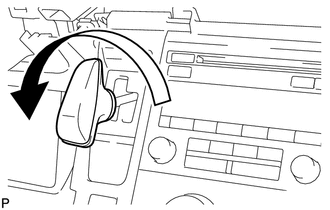
Turn the shift lever knob counterclockwise and remove the shift lever knob sub-assembly.
-
-
REMOVE INTEGRATION CONTROL AND PANEL ASSEMBLY
-
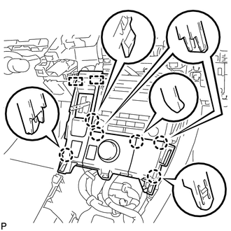
Disengage the 6 claws and 2 guides.
-
Disengage the clamp.
-
Disconnect each connector and remove the integration control and panel assembly.
-
-
REMOVE RADIO TUNER OPENING COVER WITH BRACKET (w/o Radio Receiver)
-
Remove the 4 bolts <A>.
-
Disconnect each connector and remove the radio tuner opening cover with bracket.
-
-
REMOVE RADIO RECEIVER ASSEMBLY WITH BRACKET (for Radio Receiver Type)
-
REMOVE RADIO RECEIVER ASSEMBLY WITH BRACKET (for Navigation Receiver Type)
-
REMOVE CONSOLE BOX INSERT
-
Disengage the 2 clips and 2 claws, and remove the console box insert.
-
-
REMOVE CONSOLE BOX LH
-
Remove the bolt <A>.
-
Using a clip remover, remove the clip.
-
Using a clip remover, disengage the 3 clips.
-
Disengage the 2 claws and guide, and remove the console box LH.
-
-
REMOVE FRONT NO. 2 CONSOLE BOX INSERT
-
Disengage the 5 claws and remove the front No. 2 console box insert.
-
-
REMOVE CONSOLE BOX RH
-
Remove the bolt <A>.
-
Using a clip remover, remove the clip.
-
Using a clip remover, disengage the 3 clips.
-
Disengage the 2 claws and guide, and remove the console box RH.
-
-
REMOVE TRANSMISSION INSTRUMENT PANEL SHIFT ASSEMBLY
-
REMOVE NO. 3 CONSOLE BOX MOUNTING BRACKET
-
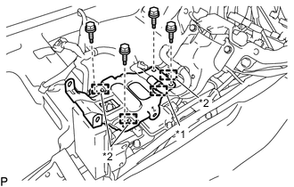
Text in Illustration *1 Clamp *2 Guide Disengage the clamp.
-
Remove the 4 bolts <A>.
-
Disengage the 3 guides and remove the No. 3 console box mounting bracket.
-
-
REMOVE NO. 1 CONSOLE BOX MOUNTING BRACKET
-
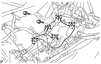
Text in Illustration *1 Clamp *2 Guide Disengage each clamp.
-
Remove the 2 bolts <A>.
-
Disengage the 2 guides and remove the No. 1 console box mounting bracket.
-
-
REMOVE MAYDAY BATTERY WITH BRACKET (w/ G-BOOK System)
-
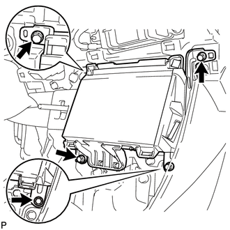
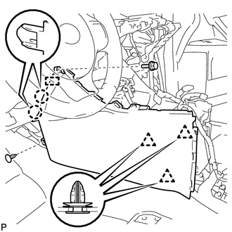
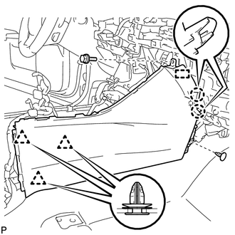
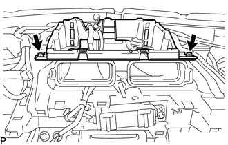
REMOVE INSTRUMENT PANEL BOX ASSEMBLY (w/ Instrument Panel Box)
-
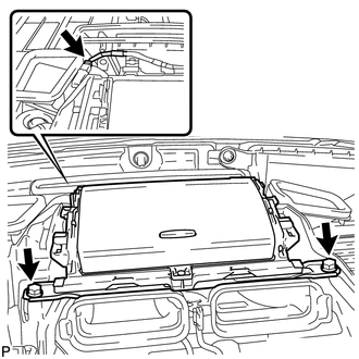
Disconnect the connector.
-
Remove the 2 bolts <A>.
-
Disengage the 2 clips and remove the instrument panel box assembly as shown in the illustration.
-
-
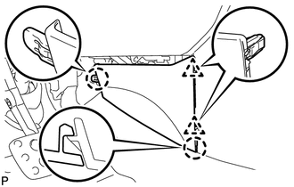
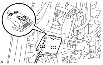
REMOVE INSTRUMENT CLUSTER FINISH PANEL RETAINER (w/ Navigation System)
-
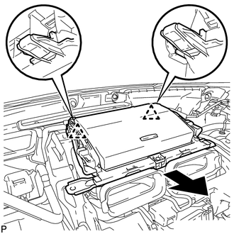
Remove the 2 bolts <A>.
-
Disengage the 2 clips as shown in the illustration.
-
Disengage the clamp and remove the instrument cluster finish panel retainer.
-
-
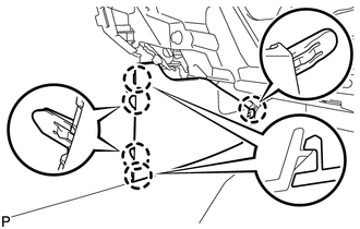
DISCONNECT HOOD LOCK CONTROL LEVER SUB-ASSEMBLY
-
Disengage the claw and 2 guides, and disconnect the hood lock control lever sub-assembly.
-
-
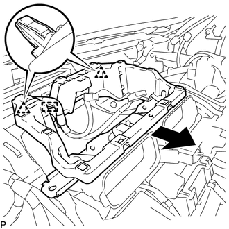
REMOVE LOWER INSTRUMENT PANEL SUB-ASSEMBLY (w/o Instrument Cluster Finish Panel)
-
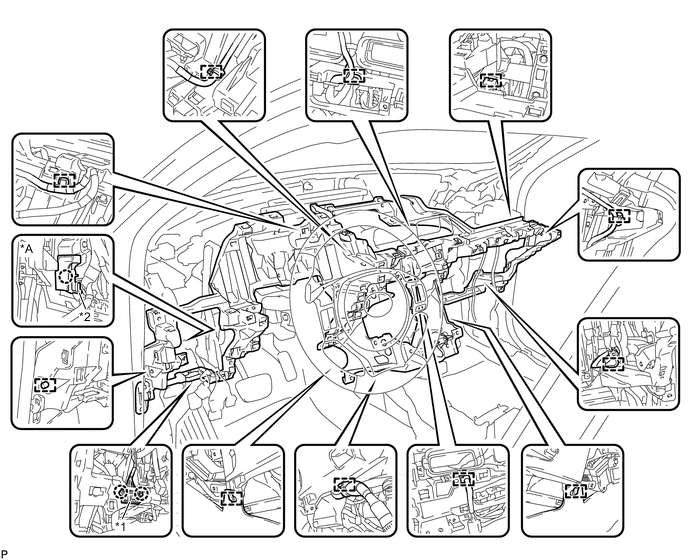
Disengage each clamp.
-
for LHD:
-
Disengage the claw and disconnect the protector.
-
-
Disengage the 2 claws and disconnect the DLC3 connector.
Text in Illustration *A for LHD - - *1 DLC3 Connector *2 Protector -
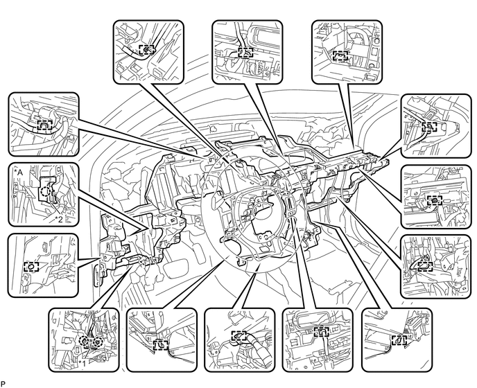
Remove the 4 bolts <A>, 10 screws <B> or <C> and screw <D>.
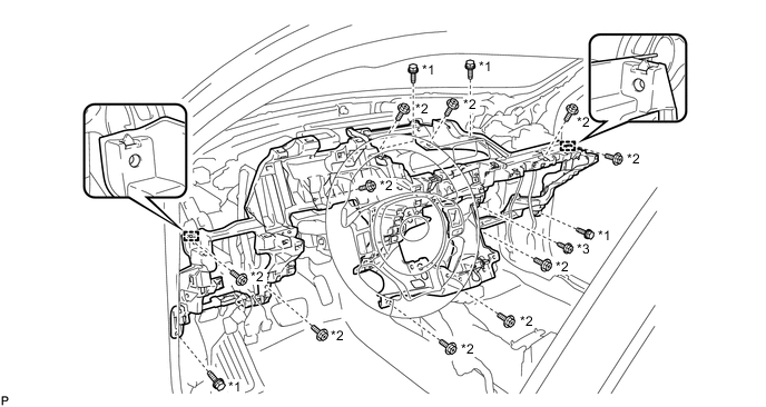
Text in Illustration *1 Bolt <A> *2 Screw <B> or <C> *3 Screw <D> - - -
Disengage the 2 guides and remove the lower instrument panel sub-assembly.
-
-
REMOVE LOWER INSTRUMENT PANEL SUB-ASSEMBLY (w/ Instrument Cluster Finish Panel)
-
Disengage each clamp.
-
for LHD:
-
Disengage the claw and disconnect the protector.
-
-
Disengage the 2 claws and disconnect the DLC3 connector.
Text in Illustration *A for LHD - - *1 DLC3 Connector *2 Protector -
Remove the 2 bolts <A>, 10 screws <B> or <C> and screw <D>.
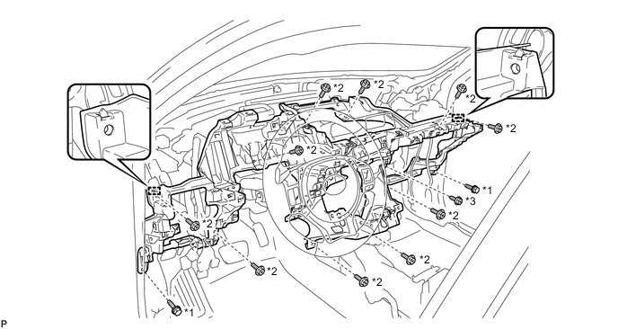
Text in Illustration *1 Bolt <A> *2 Screw <B> or <C> *3 Screw <D> - - -
Disengage the 2 guides and remove the lower instrument panel sub-assembly.
-