CONDENSER INSTALLATION
PROCEDURE
-
INSTALL COOLER CONDENSER ASSEMBLY
-
Install the cooler condenser assembly to the hybrid radiator assembly with the 4 bolts.
- Torque:
- 9.0 N*m { 92 kgf*cm, 80 in.*lbf }
-
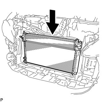
Install the cooler condenser assembly.
Tech Tips
If the condenser is replaced with a new one, add compressor oil to the new condenser.
Capacity 40 cc (1.35 fl. oz.) Compressor oil ND-11 or equivalent Note
Do not use any compressor oil other than ND-OIL 11 or equivalent. If any compressor oil other than ND-OIL 11 or equivalent is used, compressor motor insulation performance may decrease, resulting in a leakage of electric power.
-
-
INSTALL NO. 2 FAN SHROUD
for 2ZR-FXE: Click here
for 5ZR-FXE: Click here
-
INSTALL NO. 1 INVERTER BRACKET
-
CONNECT NO. 1 INVERTER COOLING HOSE
-
Using pliers, grip the claws of the clip and slide the clip to connect the No. 1 inverter cooling hose.
-
-
CONNECT NO. 5 INVERTER COOLING HOSE
-
Using pliers, grip the claws of the clip and slide the clip to connect the No. 5 inverter cooling hose.
-
-
CONNECT AIR CONDITIONING TUBE AND ACCESSORY ASSEMBLY
-
Remove the attached vinyl tape from the pipe and the connecting part of the cooler condenser assembly.
-
Apply a sufficient amount of compressor oil to a new O-ring and the fitting surface of the pipe joint.
Compressor oil ND-OIL 11 or equivalent -
Install the O-ring to the air conditioning tube and accessory assembly.
Note
-
Keep the O-ring and O-ring fitting surfaces free from dirt or foreign matter.
-
Do not use any compressor oil other than ND-OIL 11 or equivalent. If any compressor oil other than ND-OIL 11 or equivalent is used, compressor motor insulation performance may decrease, resulting in a leakage of electric power.
-
-
Install the air conditioning tube and accessory assembly to the cooler condenser assembly with the bolt.
- Torque:
- 5.4 N*m { 55 kgf*cm, 48 in.*lbf }
-
-
CONNECT COOLER REFRIGERANT DISCHARGE HOSE
-
Remove the attached vinyl tape from the hose and the connecting part of the cooler condenser assembly.
-
Apply a sufficient amount of compressor oil to a new O-ring and the fitting surface of the hose joint.
Compressor oil ND-OIL 11 or equivalent -
Install the O-ring to the cooler refrigerant discharge hose.
Note
-
Keep the O-ring and O-ring fitting surfaces free from dirt or foreign matter.
-
Do not use any compressor oil other than ND-OIL 11 or equivalent. If any compressor oil other than ND-OIL 11 or equivalent is used, compressor motor insulation performance may decrease, resulting in a leakage of electric power.
-
-
Install the cooler refrigerant discharge hose to the cooler condenser assembly with the bolt.
- Torque:
- 5.4 N*m { 55 kgf*cm, 48 in.*lbf }
-
-
INSTALL HOOD LOCK SUPPORT SUB-ASSEMBLY
-
INSTALL HIGH PITCHED HORN ASSEMBLY
-
INSTALL LOW PITCHED HORN ASSEMBLY
-
INSTALL COOL AIR INTAKE DUCT RETAINER SUB-ASSEMBLY
-
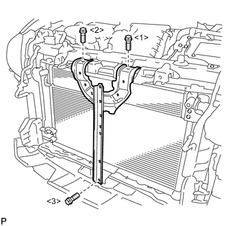
Install the cool air intake duct retainer sub-assembly with the 3 bolts.
- Torque:
- 6.2 N*m { 63 kgf*cm, 55 in.*lbf }
Note
Tighten the bolts in the order shown in the illustration to install the cool air intake duct retainer sub-assembly.
-
-
INSTALL HOOD LOCK ASSEMBLY (w/o Engine Hood Courtesy Switch)
-
INSTALL HOOD LOCK ASSEMBLY (w/ Engine Hood Courtesy Switch)
-
INSTALL MILLIMETER WAVE RADAR SENSOR ASSEMBLY (w/ Dynamic Radar Cruise Control System)
-
INSTALL FRONT BUMPER ASSEMBLY
-
CONNECT CABLE TO NEGATIVE BATTERY TERMINAL
Note
When disconnecting the cable, some systems need to be initialized after the cable is reconnected Click here.
-
INSTALL REAR FLOOR BOARD UPPER NO. 3 PLATE
-
INSTALL DECK FLOOR BOX RH
-
INSTALL REAR NO. 3 FLOOR BOARD
-
INSTALL REAR DECK FLOOR BOX
-
INSTALL REAR NO. 2 FLOOR BOARD
-
CHARGE AIR CONDITIONING SYSTEM WITH REFRIGERANT (for HFC-134a(R134a))
-
CHARGE AIR CONDITIONING SYSTEM WITH REFRIGERANT (for HFO-1234yf(R1234yf))
-
ADD COOLANT (for Inverter)
-
INSPECT FOR COOLANT LEAK (for Inverter)
-
WARM UP COMPRESSOR (for HFC-134a(R134a))
-
WARM UP COMPRESSOR (for HFO-1234yf(R1234yf))
-
INSPECT FOR REFRIGERANT LEAK (for HFC-134a(R134a))
-
INSPECT FOR REFRIGERANT LEAK (for HFO-1234yf(R1234yf))
-
ADJUST HOOD SUB-ASSEMBLY
-
ADJUST MILLIMETER WAVE RADAR SENSOR ASSEMBLY (w/ Dynamic Radar Cruise Control System)