AIRBAG SYSTEM, Diagnostic DTC:B1617/84, B1618/84

| DTC Code | DTC Name |
|---|---|
| B1617/84 | Lost Communication with Front Airbag Sensor LH |
| B1618/84 | Front Airbag Sensor LH Initialization Incomplete |
DESCRIPTION
The front airbag sensor LH circuit consists of the airbag sensor assembly and front airbag sensor LH.
The front airbag sensor LH detects impacts to the vehicle and sends signals to the airbag sensor assembly to determine if the airbag should be deployed.
These DTCs are stored when a malfunction is detected in the front airbag sensor LH circuit.
| DTC No. | DTC Detection Condition | Trouble Area |
|---|---|---|
| B1617/84 B1618/84 |
|
|
WIRING DIAGRAM
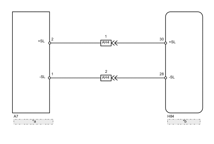
| *a | Front Airbag Sensor LH |
| *b | Airbag Sensor Assembly |
CAUTION / NOTICE / HINT
Note
After turning the power switch off, waiting time may be required before disconnecting the cable from the negative (-) auxiliary battery terminal. Therefore, make sure to read the disconnecting the cable from the negative (-) auxiliary battery terminal notices before proceeding with work Click here.
PROCEDURE
-
CHECK CONNECTORS
-
Turn the power switch off.
-
Disconnect the cable from the negative (-) auxiliary battery terminal.
CAUTION:
Wait at least 90 seconds after disconnecting the cable from the negative (-) auxiliary battery terminal to disable the SRS system.
-
Check that the connectors are properly connected to the airbag sensor assembly and front airbag sensor LH. Also check that the connectors that link the engine room main wire and instrument panel wire are properly connected.
OK The connectors are properly connected. Tech Tips
If the connectors are not connected securely, reconnect the connectors and proceed to the next inspection.
-
Disconnect the connectors from the airbag sensor assembly and front airbag sensor LH. Also disconnect the connectors that link the engine room main wire and instrument panel wire.
-
Check that the terminals of the connectors are not damaged.
OK The terminals are not deformed or damaged.
NG 
REPLACE WIRE HARNESS
OK 
-
-
CHECK FRONT AIRBAG SENSOR LH CIRCUIT (OPEN)
- SST
- 09843-18040
-
w/o Rear Pretensioner
-
Connect the connectors that link the engine room main wire and instrument panel wire.
-
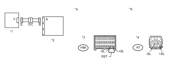
Using SST, connect terminals 30 (+SL) and 28 (-SL) of connector B.
Note
Do not forcibly insert SST into the terminals of the connector when connecting.
-
Measure the resistance according to the value(s) in the table below.
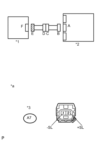
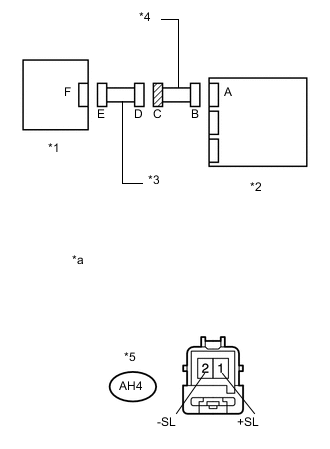
Standard Resistance Tester Connection Condition Specified Condition A7-2 (+SL) - A7-1 (-SL) Always Below 1 Ω Text in Illustration *1 Front Airbag Sensor LH *2 Airbag Sensor Assembly *3 Connector B *4 Connector E *a Front view of wire harness connector
(to Airbag Sensor Assembly)
*b Front view of wire harness connector
(to Front Airbag Sensor LH)
- SST
- 09843-18040
-
-
w/ Rear Pretensioner
-
Connect the connectors that link the engine room main wire and instrument panel wire.
-
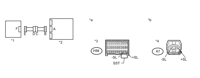
Using SST, connect terminals 30 (+SL) and 28 (-SL) of connector B.
Note
Do not forcibly insert SST into the terminals of the connector when connecting.
-
Measure the resistance according to the value(s) in the table below.
Standard Resistance Tester Connection Condition Specified Condition A7-2 (+SL) - A7-1 (-SL) Always Below 1 Ω Text in Illustration *1 Front Airbag Sensor LH *2 Airbag Sensor Assembly *3 Connector B *4 Connector E *a Front view of wire harness connector
(to Airbag Sensor Assembly)
*b Front view of wire harness connector
(to Front Airbag Sensor LH)
-
NG 
CHECK INSTRUMENT PANEL WIRE (OPEN) Click here
OK
-
CHECK FRONT AIRBAG SENSOR LH CIRCUIT (SHORT)
-
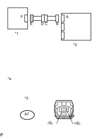
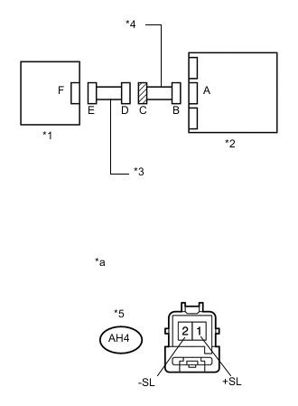
Text in Illustration *1 Front Airbag Sensor LH *2 Airbag Sensor Assembly *3 Connector E *a Front view of wire harness connector
(to Front Airbag Sensor LH)
w/o Rear Pretensioner
-
Disconnect SST from connector B.
-
Measure the resistance according to the value(s) in the table below.
Standard Resistance Tester Connection Condition Specified Condition A7-2 (+SL) - A7-1 (-SL) Always 1 MΩ or higher
-
-
Text in Illustration *1 Front Airbag Sensor LH *2 Airbag Sensor Assembly *3 Connector E *a Front view of wire harness connector
(to Front Airbag Sensor LH)
w/ Rear Pretensioner
-
Disconnect SST from connector B.
-
Measure the resistance according to the value(s) in the table below.
Standard Resistance Tester Connection Condition Specified Condition A7-2 (+SL) - A7-1 (-SL) Always 1 MΩ or higher
-
NG
CHECK INSTRUMENT PANEL WIRE (SHORT) Click here
OK
-
-
CHECK FRONT AIRBAG SENSOR LH CIRCUIT (SHORT TO B+)
-
Text in Illustration *1 Front Airbag Sensor LH *2 Airbag Sensor Assembly *3 Connector E *a Front view of wire harness connector
(to Front Airbag Sensor LH)
w/o Rear Pretensioner
-
Connect the cable to the negative (-) auxiliary battery terminal.
-
Turn the power switch on (IG).
-
Measure the voltage according to the value(s) in the table below.
Standard Voltage Tester Connection Switch Condition Specified Condition A7-2 (+SL) - Body ground Power switch on (IG) Below 1 V A7-1 (-SL) - Body ground Power switch on (IG) Below 1 V
-
-
Text in Illustration *1 Front Airbag Sensor LH *2 Airbag Sensor Assembly *3 Connector E *a Front view of wire harness connector
(to Front Airbag Sensor LH)
w/ Rear Pretensioner
-
Connect the cable to the negative (-) auxiliary battery terminal.
-
Turn the power switch on (IG).
-
Measure the voltage according to the value(s) in the table below.
Standard Voltage Tester Connection Switch Condition Specified Condition A7-2 (+SL) - Body ground Power switch on (IG) Below 1 V A7-1 (-SL) - Body ground Power switch on (IG) Below 1 V
-
NG
CHECK INSTRUMENT PANEL WIRE (SHORT TO B+) Click here
OK
-
-
CHECK FRONT AIRBAG SENSOR LH CIRCUIT (SHORT TO GROUND)
-
Text in Illustration *1 Front Airbag Sensor LH *2 Airbag Sensor Assembly *3 Connector E *a Front view of wire harness connector
(to Front Airbag Sensor LH)
w/o Rear Pretensioner
-
Turn the power switch off.
-
Disconnect the cable from the negative (-) auxiliary battery terminal.
CAUTION:
Wait at least 90 seconds after disconnecting the cable from the negative (-) auxiliary battery terminal to disable the SRS system.
-
Measure the resistance according to the value(s) in the table below.
Standard Resistance Tester Connection Condition Specified Condition A7-2 (+SL) - Body ground Always 1 MΩ or higher A7-1 (-SL) - Body ground Always 1 MΩ or higher
-
-
Text in Illustration *1 Front Airbag Sensor LH *2 Airbag Sensor Assembly *3 Connector E *a Front view of wire harness connector
(to Front Airbag Sensor LH)
w/ Rear Pretensioner
-
Turn the power switch off.
-
Disconnect the cable from the negative (-) auxiliary battery terminal.
CAUTION:
Wait at least 90 seconds after disconnecting the cable from the negative (-) auxiliary battery terminal to disable the SRS system.
-
Measure the resistance according to the value(s) in the table below.
Standard Resistance Tester Connection Condition Specified Condition A7-2 (+SL) - Body ground Always 1 MΩ or higher A7-1 (-SL) - Body ground Always 1 MΩ or higher
-
NG
CHECK INSTRUMENT PANEL WIRE (SHORT TO GROUND) Click here
OK
-
-
CHECK FRONT AIRBAG SENSOR LH
-
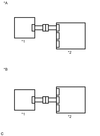
Text in Illustration *A w/o Rear Pretensioner *B w/ Rear Pretensioner *1 Front Airbag Sensor RH *2 Airbag Sensor Assembly Connect the connector to the airbag sensor assembly.
-
Interchange the front airbag sensor LH with RH and connect the connectors.
-
Connect the cable to the negative (-) auxiliary battery terminal.
-
Turn the power switch on (IG), and wait for at least 60 seconds.
-
Clear the DTCs stored in memory Click here.
-
Turn the power switch off.
-
Turn the power switch on (IG), and wait for at least 60 seconds.
-
Check for DTCs Click here.
Result Result Proceed to DTCs B1612/83, B1613/83, B1617/84 and B1618/84 are not output. A DTC B1617/84 or B1618/84 is output. B DTC B1612/83 or B1613/83 is output. C Tech Tips
Codes other than DTCs B1612/83, B1613/83, B1617/84 and B1618/84, may be output at this time, but they are not related to this check.
-
Turn the power switch off.
-
Disconnect the cable from the negative (-) auxiliary battery terminal.
CAUTION:
Wait at least 90 seconds after disconnecting the cable from the negative (-) auxiliary battery terminal to disable the SRS system.
-
Return the front airbag sensor LH and RH to their original positions and connect the connectors.
A
USE SIMULATION METHOD TO CHECK Click here
B
REPLACE AIRBAG SENSOR ASSEMBLY Click here
C
REPLACE FRONT AIRBAG SENSOR LH Click here
-
-
CHECK INSTRUMENT PANEL WIRE (OPEN)
-
w/o Rear Pretensioner
-
Disconnect the instrument panel wire connector from the engine room main wire.
Tech Tips
SST has already been inserted into connector B.
-
Measure the resistance according to the value(s) in the table below.
Standard Resistance Tester Connection Condition Specified Condition AH4-1 (+SL) - AH4-2 (-SL) Always Below 1 Ω -
Disconnect SST from connector B.
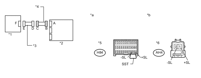
Text in Illustration *1 Front Airbag Sensor LH *2 Airbag Sensor Assembly *3 Engine Room Main Wire *4 Instrument Panel Wire *5 Connector B *6 Connector C *a Front view of wire harness connector
(to Airbag Sensor Assembly)
*b Front view of wire harness connector
(to Engine Room Main Wire)
-
-
w/ Rear Pretensioner
-
Disconnect the instrument panel wire connector from the engine room main wire.
Tech Tips
SST has already been inserted into connector B.
-
Measure the resistance according to the value(s) in the table below.
Standard Resistance Tester Connection Condition Specified Condition AH4-1 (+SL) - AH4-2 (-SL) Always Below 1 Ω -
Disconnect SST from connector B.
Text in Illustration *1 Front Airbag Sensor LH *2 Airbag Sensor Assembly *3 Engine Room Main Wire *4 Instrument Panel Wire *5 Connector B *6 Connector C *a Front view of wire harness connector
(to Airbag Sensor Assembly)
*b Front view of wire harness connector
(to Engine Room Main Wire)
-
OK
REPLACE ENGINE ROOM MAIN WIRE
NG
REPLACE INSTRUMENT PANEL WIRE
-
-
CHECK INSTRUMENT PANEL WIRE (SHORT)
-
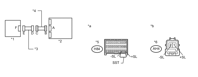
Text in Illustration *1 Front Airbag Sensor LH *2 Airbag Sensor Assembly *3 Engine Room Main Wire *4 Instrument Panel Wire *5 Connector C *a Front view of wire harness connector
(to Engine Room Main Wire)
w/o Rear Pretensioner
-
Disconnect the instrument panel wire connector from the engine room main wire.
-
Measure the resistance according to the value(s) in the table below.
Standard Resistance Tester Connection Condition Specified Condition AH4-1 (+SL) - AH4-2 (-SL) Always 1 MΩ or higher
-
-
Text in Illustration *1 Front Airbag Sensor LH *2 Airbag Sensor Assembly *3 Engine Room Main Wire *4 Instrument Panel Wire *5 Connector C *a Front view of wire harness connector
(to Engine Room Main Wire)
w/ Rear Pretensioner
-
Disconnect the instrument panel wire connector from the engine room main wire.
-
Measure the resistance according to the value(s) in the table below.
Standard Resistance Tester Connection Condition Specified Condition AH4-1 (+SL) - AH4-2 (-SL) Always 1 MΩ or higher
-
OK
REPLACE ENGINE ROOM MAIN WIRE
NG
REPLACE INSTRUMENT PANEL WIRE
-
-
CHECK INSTRUMENT PANEL WIRE (SHORT TO B+)
-
Text in Illustration *1 Front Airbag Sensor LH *2 Airbag Sensor Assembly *3 Engine Room Main Wire *4 Instrument Panel Wire *5 Connector C *a Front view of wire harness connector
(to Engine Room Main Wire)
w/o Rear Pretensioner
-
Turn the power switch off.
-
Disconnect the cable from the negative (-) auxiliary battery terminal.
CAUTION:
Wait at least 90 seconds after disconnecting the cable from the negative (-) auxiliary battery terminal to disable the SRS system.
-
Disconnect the instrument panel wire connector from the engine room main wire.
-
Connect the cable to the negative (-) auxiliary battery terminal.
-
Turn the power switch on (IG).
-
Measure the voltage according to the value(s) in the table below.
Standard Voltage Tester Connection Switch Condition Specified Condition AH4-1 (+SL) - Body ground Power switch on (IG) Below 1 V AH4-2 (-SL) - Body ground Power switch on (IG) Below 1 V
-
-
Text in Illustration *1 Front Airbag Sensor LH *2 Airbag Sensor Assembly *3 Engine Room Main Wire *4 Instrument Panel Wire *5 Connector C *a Front view of wire harness connector
(to Engine Room Main Wire)
w/ Rear Pretensioner
-
Turn the power switch off.
-
Disconnect the cable from the negative (-) auxiliary battery terminal.
CAUTION:
Wait at least 90 seconds after disconnecting the cable from the negative (-) auxiliary battery terminal to disable the SRS system.
-
Disconnect the instrument panel wire connector from the engine room main wire.
-
Connect the cable to the negative (-) auxiliary battery terminal.
-
Turn the power switch on (IG).
-
Measure the voltage according to the value(s) in the table below.
Standard Voltage Tester Connection Switch Condition Specified Condition AH4-1 (+SL) - Body ground Power switch on (IG) Below 1 V AH4-2 (-SL) - Body ground Power switch on (IG) Below 1 V
-
OK
REPLACE ENGINE ROOM MAIN WIRE
NG
REPLACE INSTRUMENT PANEL WIRE
-
-
CHECK INSTRUMENT PANEL WIRE (SHORT TO GROUND)
-
Text in Illustration *1 Front Airbag Sensor LH *2 Airbag Sensor Assembly *3 Engine Room Main Wire *4 Instrument Panel Wire *5 Connector C *a Front view of wire harness connector
(to Engine Room Main Wire)
w/o Rear Pretensioner
-
Disconnect the instrument panel wire connector from the engine room main wire.
-
Measure the resistance according to the value(s) in the table below.
Standard Resistance Tester Connection Condition Specified Condition AH4-1 (+SL) - Body ground Always 1 MΩ or higher AH4-2 (-SL) - Body ground Always 1 MΩ or higher
-
-
Text in Illustration *1 Front Airbag Sensor LH *2 Airbag Sensor Assembly *3 Engine Room Main Wire *4 Instrument Panel Wire *5 Connector C *a Front view of wire harness connector
(to Engine Room Main Wire)
w/ Rear Pretensioner
-
Disconnect the instrument panel wire connector from the engine room main wire.
-
Measure the resistance according to the value(s) in the table below.
Standard Resistance Tester Connection Condition Specified Condition AH4-1 (+SL) - Body ground Always 1 MΩ or higher AH4-2 (-SL) - Body ground Always 1 MΩ or higher
-
OK
REPLACE ENGINE ROOM MAIN WIRE
NG
REPLACE INSTRUMENT PANEL WIRE
-