CAN COMMUNICATION SYSTEM, Diagnostic DTC:U1002
| DTC Code | DTC Name |
|---|---|
| U1002 | Lost Communication with Gateway Module (Power Management2) |
DESCRIPTION
-
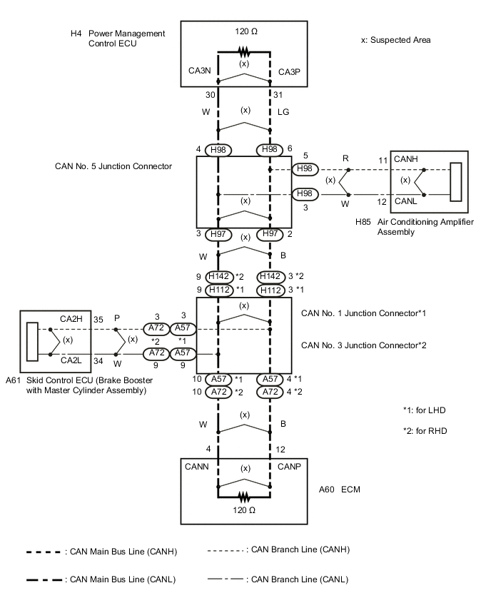
The power management control ECU will store this DTC when no signals can be received from the ECUs that have been memorized as those that are connected to the sub bus 12.
-
When the power management control ECU receives a response signal from the ECUs connected to the sub bus 12, the power management control ECU recognizes and memorizes that the ECU is connected to the sub bus 12. Based on this memorized data, the power management control ECU monitors for malfunctions in the ECUs connected to the sub bus 12 when communicating with those ECUs. If the power management control ECU cannot receive response signals from the ECUs that have been memorized as those connected to the sub bus 12, the power management control ECU determines that a malfunction exists.
| DTC No. | DTC Detection Condition | Trouble Area |
|---|---|---|
| U1002 | Power management control ECU cannot receive signals from all ECUs that have been memorized as those connected to the sub bus 12. |
|
Tech Tips
This diagnosis procedure is for when DTC U1002 is output by the power management control ECU (GTS display: PM2 Gateway).
WIRING DIAGRAM
CAUTION / NOTICE / HINT
Note
-
After turning the power switch off, waiting time may be required before disconnecting the cable from the negative (-) auxiliary battery terminal. Therefore, make sure to read the disconnecting the cable from the negative (-) auxiliary battery terminal notices before proceeding with work Click here.
-
Turn the power switch off before measuring the resistances between CAN main bus lines and between CAN branch lines.
-
Turn the power switch off before inspecting CAN bus lines for a ground short.
-
After the power switch is turned off, check that the key reminder warning system and light reminder warning system are not operating.
-
Before measuring the resistance, leave the vehicle as is for at least 1 minute and do not operate the power switch, any other switches or the doors. If any doors need to be opened in order to check connectors, open the doors and leave them open.
Tech Tips
-
Operating the power switch, any other switches or a door triggers related ECU and sensor communication on the CAN. This communication will cause the resistance value to change.
-
Even after DTCs are cleared, if a DTC is stored again after driving the vehicle for a while, the malfunction may be occurring due to vibration of the vehicle. In such a case, wiggling the ECUs or wire harness while performing the inspection below may help determine the cause of the malfunction.
PROCEDURE
-
CHECK SUB BUS 12 LINES
-
Turn the power switch off.
-
Disconnect the cable from the negative (-) auxiliary battery terminal.
-
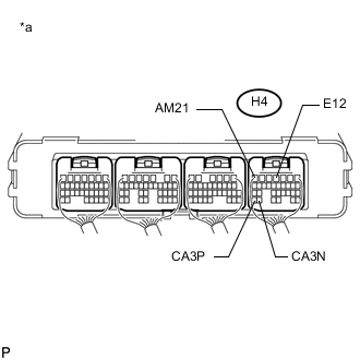
Text in Illustration *a Component with harness connector
(Power Management Control ECU)
Measure the resistance according to the value(s) in the table below.
Standard Resistance Tester Connection Condition Specified Condition Result H4-31 (CA3P) - H4-30 (CA3N) Cable disconnected from negative (-) auxiliary battery terminal 54 to 69 Ω Below 54 Ω:
Short circuit between bus lines
70 Ω or higher:
Open circuit in a main bus line
H4-31 (CA3P) - H4-4 (E12) Cable disconnected from negative (-) auxiliary battery terminal 200 Ω or higher Below 200 Ω:
CANH ground short
H4-30 (CA3N) - H4-4 (E12) Cable disconnected from negative (-) auxiliary battery terminal 200 Ω or higher Below 200 Ω:
CANL ground short
-
Measure the resistance according to the value(s) in the table below.
Standard Resistance Tester Connection Condition Specified Condition Result H4-31 (CA3P) - H4-7 (AM21) Cable disconnected from negative (-) auxiliary battery terminal 6 kΩ or higher Below 6 kΩ:
CANH +B short
H4-30 (CA3N) - H4-7 (AM21) Cable disconnected from negative (-) auxiliary battery terminal 6 kΩ or higher Below 6 kΩ:
CANL +B short
Result Result Proceed to OK A Open circuit in CAN main bus line B Short circuit between bus lines C
-
Ground short
-
+B short
D -
B 
CHECK FOR OPEN IN CAN BUS LINES (POWER MANAGEMENT CONTROL ECU) Click here
C
CHECK FOR SHORT IN CAN BUS LINES (POWER MANAGEMENT CONTROL ECU) Click here
D
CHECK FOR SHORT IN CAN BUS LINE (CAN NO. 5 J/C) Click here
A 
-
-
CHECK FOR DTC OUTPUT
-
Reconnect the cable to the negative (-) auxiliary battery terminal.
-
Clear the DTCs.
-
Turn the power switch off.
-
Turn the power switch on (IG) and recheck for DTCs.
Result Result Proceed to U1002 is output from power management control ECU
(GTS display/PM2 Gateway)
A Other DTC is output B
A 
REPAIR OR REPLACE POWER MANAGEMENT CONTROL ECU Click here
B
GO TO DIAGNOSIS PROCEDURE INDICATED BY OUTPUT DTC
-
-
CHECK FOR OPEN IN CAN BUS LINES (POWER MANAGEMENT CONTROL ECU)
-
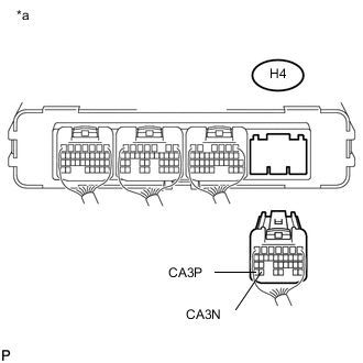
Text in Illustration *a Rear view of wire harness connector
(to Power Management Control ECU)
Disconnect the power management control ECU connector.
-
Measure the resistance according to the value(s) in the table below.
Standard Resistance Tester Connection Condition Specified Condition H4-31 (CA3P) - H4-30 (CA3N) Cable disconnected from negative (-) auxiliary battery terminal 108 to 132 Ω Result Result Proceed to OK A NG (for LHD) B NG (for RHD) C
A
REPAIR OR REPLACE POWER MANAGEMENT CONTROL ECU Click here
C
CHECK FOR OPEN IN CAN BUS LINES (CAN NO. 5 J/C - CAN NO. 3 J/C) Click here
B
-
-
CHECK FOR OPEN IN CAN BUS LINES (CAN NO. 5 J/C - CAN NO. 1 J/C)
-
Reconnect the power management control ECU connector.
-
Disconnect the wire harness connector from CAN No. 5 junction connector front side.
-
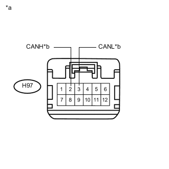
Text in Illustration *a Front view of wire harness connector
(to CAN No. 5 Junction Connector)
*b to CAN No. 1 Junction Connector Measure the resistance according to the value(s) in the table below.
Standard Resistance Tester Connection Condition Specified Condition H97-2 (CANH) - H97-3 (CANL) Cable disconnected from negative (-) auxiliary battery terminal 108 to 132 Ω
NG
CHECK FOR OPEN IN CAN BUS LINES (CAN NO. 1 J/C - CAN NO. 5 J/C) Click here
OK
-
-
CHECK FOR OPEN IN CAN BUS LINES (CAN NO. 5 J/C - POWER MANAGEMENT CONTROL ECU)
-
Reconnect the wire harness connector to the CAN No. 5 junction connector front side.
-
Disconnect the wire harness connector from the CAN No. 5 junction connector rear side.
-
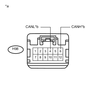
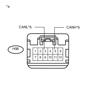
Text in Illustration *a Front view of wire harness connector
(to CAN No. 5 Junction Connector)
*b to Power Management Control ECU Measure the resistance according to the value(s) in the table below.
Standard Resistance Tester Connection Condition Specified Condition H98-6 (CANH) - H98-4 (CANL) Cable disconnected from negative (-) auxiliary battery terminal 108 to 132 Ω
OK
REPLACE CAN NO. 5 JUNCTION CONNECTOR
NG
REPAIR OR REPLACE CAN MAIN BUS LINE OR CONNECTOR (CAN NO. 5 J/C - POWER MANAGEMENT CONTROL ECU)
-
-
CHECK FOR OPEN IN CAN BUS LINES (CAN NO. 1 J/C - CAN NO. 5 J/C)
-
Reconnect the wire harness connector to the CAN No. 5 junction connector rear side.
-
Disconnect the instrument panel wire from the CAN No. 1 junction connector.
-
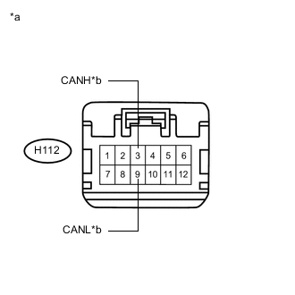
Text in Illustration *a Front view of wire harness connector
(to CAN No. 1 Junction Connector)
*b to CAN No. 5 Junction Connector Measure the resistance according to the value(s) in the table below.
Standard Resistance Tester Connection Condition Specified Condition H112-3 (CANH) - H112-9 (CANL) Cable disconnected from negative (-) auxiliary battery terminal 108 to 132 Ω
NG
REPAIR OR REPLACE CAN MAIN BUS LINE OR CONNECTOR (CAN NO. 1 J/C - CAN NO. 5 J/C)
OK
-
-
CHECK FOR OPEN IN CAN BUS LINES (CAN NO. 1 J/C - ECM)
-
Reconnect the instrument panel wire to the CAN No. 1 junction connector.
-
Disconnect the engine room main wire from the CAN No. 1 junction connector.
-
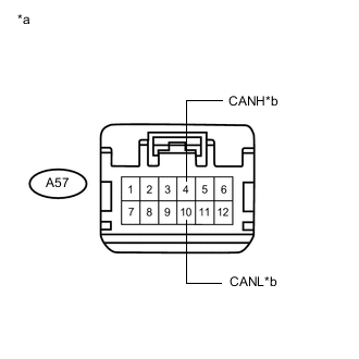
Text in Illustration *a Front view of wire harness connector
(to CAN No. 1 Junction Connector)
*b to ECM Measure the resistance according to the value(s) in the table below.
Standard Resistance Tester Connection Condition Specified Condition A57-4 (CANH) - A57-10 (CANL) Cable disconnected from negative (-) auxiliary battery terminal 108 to 132 Ω
OK
REPLACE CAN NO. 1 JUNCTION CONNECTOR
NG
-
-
CHECK FOR OPEN IN CAN BUS LINES (ECM)
-
Reconnect the engine room main wire to the CAN No. 1 junction connector.
-
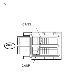
Text in Illustration *a Front view of wire harness connector
(to ECM)
Disconnect the ECM connector.
-
Measure the resistance according to the value(s) in the table below.
Standard Resistance Tester Connection Condition Specified Condition A60-12 (CANP) - A60-4 (CANN) Cable disconnected from negative (-) auxiliary battery terminal 108 to 132 Ω Result Result Proceed to OK (for 2ZR-FXE) A OK (for 5ZR-FXE) B NG C
A
REPLACE ECM Click here
B
REPLACE ECM Click here
C
REPAIR OR REPLACE CAN MAIN BUS LINE OR CONNECTOR (CAN NO. 1 J/C - ECM)
-
-
CHECK FOR OPEN IN CAN BUS LINES (CAN NO. 5 J/C - CAN NO. 3 J/C)
-
Reconnect the power management control ECU connector.
-
Disconnect the wire harness connector from CAN No. 5 junction connector front side.
-
Text in Illustration *a Front view of wire harness connector
(to CAN No. 5 Junction Connector)
*b to CAN No. 3 Junction Connector Measure the resistance according to the value(s) in the table below.
Standard Resistance Tester Connection Condition Specified Condition H97-2 (CANH) - H97-3 (CANL) Cable disconnected from negative (-) auxiliary battery terminal 108 to 132 Ω
NG
CHECK FOR OPEN IN CAN BUS LINES (CAN NO. 3 J/C - CAN NO. 5 J/C) Click here
OK
-
-
CHECK FOR OPEN IN CAN BUS LINES (CAN NO. 5 J/C - POWER MANAGEMENT CONTROL ECU)
-
Reconnect the wire harness connector to the CAN No. 5 junction connector front side.
-
Disconnect the wire harness connector from the CAN No. 5 junction connector rear side.
-
Text in Illustration *a Front view of wire harness connector
(to CAN No. 5 Junction Connector)
*b to Power Management Control ECU Measure the resistance according to the value(s) in the table below.
Standard Resistance Tester Connection Condition Specified Condition H98-6 (CANH) - H98-4 (CANL) Cable disconnected from negative (-) auxiliary battery terminal 108 to 132 Ω
OK
REPLACE CAN NO. 5 JUNCTION CONNECTOR
NG
REPAIR OR REPLACE CAN MAIN BUS LINE OR CONNECTOR (CAN NO. 5 J/C - POWER MANAGEMENT CONTROL ECU)
-
-
CHECK FOR OPEN IN CAN BUS LINES (CAN NO. 3 J/C - CAN NO. 5 J/C)
-
Reconnect the wire harness connector to the CAN No. 5 junction connector rear side.
-
Disconnect the instrument panel wire from the CAN No. 3 junction connector.
-
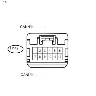
Text in Illustration *a Front view of wire harness connector
(to CAN No. 3 Junction Connector)
*b to CAN No. 5 Junction Connector Measure the resistance according to the value(s) in the table below.
Standard Resistance Tester Connection Condition Specified Condition H142-3 (CANH) - H142-9 (CANL) Cable disconnected from negative (-) auxiliary battery terminal 108 to 132 Ω
NG
REPAIR OR REPLACE CAN MAIN BUS LINE OR CONNECTOR (CAN NO. 3 J/C - CAN NO. 5 J/C)
OK
-
-
CHECK FOR OPEN IN CAN BUS LINE (CAN NO. 3 J/C - ECM)
-
Reconnect the instrument panel wire to the CAN No. 3 junction connector.
-
Disconnect the engine room main wire from the CAN No. 3 junction connector.
-

Text in Illustration *a Front view of wire harness connector
(to CAN No. 3 Junction Connector)
*b to ECM Measure the resistance according to the value(s) in the table below.
Standard Resistance Tester Connection Condition Specified Condition A72-4 (CANH) - A72-10 (CANL) Cable disconnected from negative (-) auxiliary battery terminal 108 to 132 Ω
OK
REPLACE CAN NO. 3 JUNCTION CONNECTOR
NG
-
-
CHECK FOR OPEN IN CAN BUS LINES (ECM)
-
Reconnect the engine room main wire to the CAN No. 3 junction connector.
-
Text in Illustration *a Front view of wire harness connector
(to ECM)
Disconnect the ECM connector.
-
Measure the resistance according to the value(s) in the table below.
Standard Resistance Tester Connection Condition Specified Condition A60-12 (CANP) - A60-4 (CANN) Cable disconnected from negative (-) auxiliary battery terminal 108 to 132 Ω
OK
REPLACE ECM Click here
NG
REPAIR OR REPLACE CAN MAIN BUS LINE OR CONNECTOR (CAN NO. 3 J/C - ECM)
-
-
CHECK FOR SHORT IN CAN BUS LINES (POWER MANAGEMENT CONTROL ECU)
-
Text in Illustration *a Rear view of wire harness connector
(to Power Management Control ECU)
Disconnect the power management control ECU connector.
-
Measure the resistance according to the value(s) in the table below.
Standard Resistance Tester Connection Condition Specified Condition H4-31 (CA3P) - H4-30 (CA3N) Cable disconnected from negative (-) auxiliary battery terminal 108 to 132 Ω
OK
REPAIR OR REPLACE POWER MANAGEMENT CONTROL ECU Click here
NG
-
-
CHECK FOR SHORT IN CAN BUS LINES (CAN NO. 5 J/C - POWER MANAGEMENT CONTROL ECU)
-
Reconnect the power management control ECU connector.
-
Disconnect the wire harness connector from the CAN No. 5 junction connector rear side.
-
Text in Illustration *a Front view of wire harness connector
(to CAN No. 5 Junction Connector)
*b to Power Management Control ECU Measure the resistance according to the value(s) in the table below.
Standard Resistance Tester Connection Condition Specified Condition H98-6 (CANH) - H98-4 (CANL) Cable disconnected from negative (-) auxiliary battery terminal 108 to 132 Ω Result Result Proceed to OK (for LHD) A OK (for RHD) B NG C
B
CHECK FOR SHORT IN CAN BUS LINES (CAN NO. 5 J/C - CAN NO. 3 J/C) Click here
C
REPAIR OR REPLACE CAN MAIN BUS LINE OR CONNECTOR (CAN NO. 5 J/C - POWER MANAGEMENT CONTROL ECU)
A
-
-
CHECK FOR SHORT IN CAN BUS LINES (CAN NO. 5 J/C - CAN NO. 1 J/C)
-
Disconnect the wire harness connector from CAN No. 5 junction connector front side.
-
Text in Illustration *a Front view of wire harness connector
(to CAN No. 5 Junction Connector)
*b to CAN No. 1 Junction Connector Measure the resistance according to the value(s) in the table below.
Standard Resistance Tester Connection Condition Specified Condition H97-2 (CANH) - H97-3 (CANL) Cable disconnected from negative (-) auxiliary battery terminal 108 to 132 Ω
NG
CHECK FOR SHORT IN CAN BUS LINES (CAN NO. 1 J/C - CAN NO. 5 J/C) Click here
OK
-
-
CHECK FOR SHORT IN CAN BUS LINES (CAN NO. 5 J/C - AIR CONDITIONING AMPLIFIER ASSEMBLY)
-
Disconnect the air conditioning amplifier assembly connector.
-
Text in Illustration *a Front view of wire harness connector
(to CAN No. 5 Junction Connector)
*b to Air Conditioning Amplifier Assembly Measure the resistance according to the value(s) in the table below.
Standard Resistance Tester Connection Condition Specified Condition H98-5 (CANH) - H98-3 (CANL) Cable disconnected from negative (-) auxiliary battery terminal 1 MΩ or higher
NG
REPAIR OR REPLACE CAN BRANCH LINE OR CONNECTOR (CAN NO. 5 J/C - AIR CONDITIONING AMPLIFIER ASSEMBLY)
OK
-
-
CHECK FOR SHORT IN CAN BUS LINES (AIR CONDITIONING AMPLIFIER ASSEMBLY)
-
Reconnect the wire harness connector to the CAN No. 5 junction connector front side and rear side.
-
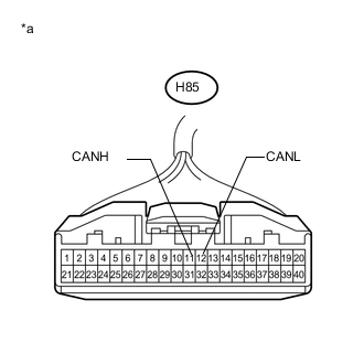
Text in Illustration *a Front view of wire harness connector
(to Air Conditioning Amplifier Assembly)
Measure the resistance according to the value(s) in the table below.
Standard Resistance Tester Connection Condition Specified Condition H85-11 (CANH) - H85-12 (CANL) Cable disconnected from negative (-) auxiliary battery terminal 54 to 69 Ω
OK
REPLACE AIR CONDITIONING AMPLIFIER ASSEMBLY Click here
NG
REPLACE CAN NO. 5 JUNCTION CONNECTOR
-
-
CHECK FOR SHORT IN CAN BUS LINES (CAN NO. 1 J/C - CAN NO. 5 J/C)
-
Reconnect the wire harness connector to the CAN No. 5 junction connector front side and rear side.
-
Disconnect the instrument panel wire from the CAN No. 1 junction connector.
-
Text in Illustration *a Front view of wire harness connector
(to CAN No. 1 Junction Connector)
*b to CAN No. 5 Junction Connector Measure the resistance according to the value(s) in the table below.
Standard Resistance Tester Connection Condition Specified Condition H112-3 (CANH) - H112-9 (CANL) Cable disconnected from negative (-) auxiliary battery terminal 108 to 132 Ω
NG
REPAIR OR REPLACE CAN MAIN BUS LINE OR CONNECTOR (CAN NO. 1 J/C - CAN NO. 5 J/C)
OK
-
-
CHECK FOR SHORT IN CAN BUS LINES (CAN NO. 1 J/C - ECM)
-
Disconnect the engine room main wire from the CAN No. 1 junction connector.
-
Text in Illustration *a Front view of wire harness connector
(to CAN No. 1 Junction Connector)
*b to ECM Measure the resistance according to the value(s) in the table below.
Standard Resistance Tester Connection Condition Specified Condition A57-4 (CANH) - A57-10 (CANL) Cable disconnected from negative (-) auxiliary battery terminal 108 to 132 Ω
NG
CHECK FOR SHORT IN CAN BUS LINES (ECM) Click here
OK
-
-
CHECK FOR SHORT IN CAN BUS LINES (CAN NO. 1 J/C - SKID CONTROL ECU)
-
Disconnect the skid control ECU (brake booster with master cylinder assembly) connector.
-

Text in Illustration *a Front view of wire harness connector
(to CAN No. 1 Junction Connector)
*b to Skid Control ECU Measure the resistance according to the value(s) in the table below.
Standard Resistance Tester Connection Condition Specified Condition A57-3 (CANH) - A57-9 (CANL) Cable disconnected from negative (-) auxiliary battery terminal 1 MΩ or higher
NG
REPAIR OR REPLACE CAN BRANCH LINE OR CONNECTOR (CAN NO. 1 J/C - SKID CONTROL ECU)
OK
-
-
CHECK FOR SHORT IN CAN BUS LINES (SKID CONTROL ECU)
-
Reconnect the instrument panel wire and engine room main wire to the CAN No. 1 junction connector.
-
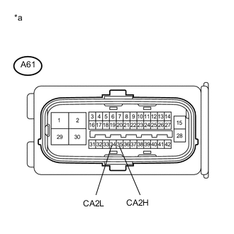
Text in Illustration *a Front view of wire harness connector
(to Skid Control ECU)
Measure the resistance according to the value(s) in the table below.
Standard Resistance Tester Connection Condition Specified Condition A61-35 (CA2H) - A61-34 (CA2L) Cable disconnected from negative (-) auxiliary battery terminal 54 to 69 Ω
OK
REPLACE BRAKE BOOSTER WITH MASTER CYLINDER ASSEMBLY (SKID CONTROL ECU) Click here
NG
REPLACE CAN NO. 1 JUNCTION CONNECTOR
-
-
CHECK FOR SHORT IN CAN BUS LINES (ECM)
-
Reconnect the instrument panel wire and engine room main wire to the CAN No. 1 junction connector.
-
Text in Illustration *a Front view of wire harness connector
(to ECM)
Disconnect the ECM connector.
-
Measure the resistance according to the value(s) in the table below.
Standard Resistance Tester Connection Condition Specified Condition A60-12 (CANP) - A60-4 (CANN) Cable disconnected from negative (-) auxiliary battery terminal 108 to 132 Ω Result Result Proceed to OK (for 2ZR-FXE) A OK (for 5ZR-FXE) B NG C
A
REPLACE ECM Click here
B
REPLACE ECM Click here
C
REPAIR OR REPLACE CAN MAIN BUS LINE OR CONNECTOR (CAN NO. 1 J/C - ECM)
-
-
CHECK FOR SHORT IN CAN BUS LINES (CAN NO. 5 J/C - CAN NO. 3 J/C)
-
Disconnect the wire harness connector from CAN No. 5 junction connector front side.
-
Text in Illustration *a Front view of wire harness connector
(to CAN No. 5 Junction Connector)
*b to CAN No. 3 Junction Connector Measure the resistance according to the value(s) in the table below.
Standard Resistance Tester Connection Condition Specified Condition H97-2 (CANH) - H97-3 (CANL) Cable disconnected from negative (-) auxiliary battery terminal 108 to 132 Ω
NG
CHECK FOR SHORT IN CAN BUS LINES (CAN NO. 3 J/C - CAN NO. 5 J/C) Click here
OK
-
-
CHECK FOR SHORT IN CAN BUS LINES (CAN NO. 5 J/C - AIR CONDITIONING AMPLIFIER ASSEMBLY)
-
Disconnect the air conditioning amplifier assembly connector.
-
Text in Illustration *a Front view of wire harness connector
(to CAN No. 5 Junction Connector)
*b to Air Conditioning Amplifier Assembly Measure the resistance according to the value(s) in the table below.
Standard Resistance Tester Connection Condition Specified Condition H98-5 (CANH) - H98-3 (CANL) Cable disconnected from negative (-) auxiliary battery terminal 1 MΩ or higher
NG
REPAIR OR REPLACE CAN BRANCH LINE OR CONNECTOR (CAN NO. 5 J/C - AIR CONDITIONING AMPLIFIER ASSEMBLY)
OK
-
-
CHECK FOR SHORT IN CAN BUS LINES (AIR CONDITIONING AMPLIFIER ASSEMBLY)
-
Reconnect the wire harness connector to the CAN No. 5 junction connector front side and rear side.
-
Text in Illustration *a Front view of wire harness connector
(to Air Conditioning Amplifier Assembly)
Measure the resistance according to the value(s) in the table below.
Standard Resistance Tester Connection Condition Specified Condition H85-11 (CANH) - H85-12 (CANL) Cable disconnected from negative (-) auxiliary battery terminal 54 to 69 Ω
OK
REPLACE AIR CONDITIONING AMPLIFIER ASSEMBLY Click here
NG
REPLACE CAN NO. 5 JUNCTION CONNECTOR
-
-
CHECK FOR SHORT IN CAN BUS LINES (CAN NO. 3 J/C - CAN NO. 5 J/C)
-
Reconnect the wire harness connector to the CAN No. 5 junction connector front side and rear side.
-
Disconnect the instrument panel wire from the CAN No. 3 junction connector.
-
Text in Illustration *a Front view of wire harness connector
(to CAN No. 3 Junction Connector)
*b to CAN No. 5 Junction Connector Measure the resistance according to the value(s) in the table below.
Standard Resistance Tester Connection Condition Specified Condition H142-3 (CANH) - H142-9 (CANL) Cable disconnected from negative (-) auxiliary battery terminal 108 to 132 Ω
NG
REPAIR OR REPLACE CAN MAIN BUS LINE OR CONNECTOR (CAN NO. 3 J/C - CAN NO. 5 J/C)
OK
-
-
CHECK FOR SHORT IN CAN BUS LINES (CAN NO. 3 J/C - ECM)
-
Disconnect the engine room main wire from the CAN No. 3 junction connector.
-
Text in Illustration *a Front view of wire harness connector
(to CAN No. 3 Junction Connector)
*b to ECM Measure the resistance according to the value(s) in the table below.
Standard Resistance Tester Connection Condition Specified Condition A72-4 (CANH) - A72-10 (CANL) Cable disconnected from negative (-) auxiliary battery terminal 108 to 132 Ω
NG
CHECK FOR SHORT IN CAN BUS LINES (ECM) Click here
OK
-
-
CHECK FOR SHORT IN CAN BUS LINES (CAN NO. 3 J/C - SKID CONTROL ECU)
-
Disconnect the skid control ECU (brake booster with master cylinder assembly) connector.
-
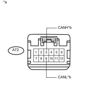
Text in Illustration *a Front view of wire harness connector
(to CAN No. 3 Junction Connector)
*b to Skid Control ECU Measure the resistance according to the value(s) in the table below.
Standard Resistance Tester Connection Condition Specified Condition A72-3 (CANH) - A72-9 (CANL) Cable disconnected from negative (-) auxiliary battery terminal 1 MΩ or higher
NG
REPAIR OR REPLACE CAN BRANCH LINE OR CONNECTOR (CAN NO. 3 J/C - SKID CONTROL ECU)
OK
-
-
CHECK FOR SHORT IN CAN BUS LINES (SKID CONTROL ECU)
-
Reconnect the instrument panel wire and engine room main wire to the CAN No. 3 junction connector.
-
Text in Illustration *a Front view of wire harness connector
(to Skid Control ECU)
Measure the resistance according to the value(s) in the table below.
Standard Resistance Tester Connection Condition Specified Condition A61-35 (CA2H) - A61-34 (CA2L) Cable disconnected from negative (-) auxiliary battery terminal 54 to 69 Ω
OK
REPLACE BRAKE BOOSTER WITH MASTER CYLINDER ASSEMBLY (SKID CONTROL ECU) Click here
NG
REPLACE CAN NO. 3 JUNCTION CONNECTOR
-
-
CHECK FOR SHORT IN CAN BUS LINES (ECM)
-
Reconnect the instrument panel wire and engine room main wire to the CAN No. 3 junction connector.
-
Text in Illustration *a Front view of wire harness connector
(to ECM)
Disconnect the ECM connector.
-
Measure the resistance according to the value(s) in the table below.
Standard Resistance Tester Connection Condition Specified Condition A60-12 (CANP) - A60-4 (CANN) Cable disconnected from negative (-) auxiliary battery terminal 108 to 132 Ω
OK
REPLACE ECM Click here
NG
REPAIR OR REPLACE CAN MAIN BUS LINE OR CONNECTOR (CAN NO. 3 J/C - ECM)
-
-
CHECK FOR SHORT IN CAN BUS LINE (CAN NO. 5 J/C)
-
Disconnect the wire harness connector from the CAN No. 5 junction connector rear side.
-
Measure the resistance according to the value(s) in the table below.
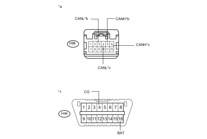
Standard Resistance Tester Connection Condition Specified Condition Purpose Connected to H98-6 (CANH) - H44-4 (CG) Cable disconnected from negative (-) auxiliary battery terminal 200 Ω or higher Inspection for CANH ground short Power management control ECU H98-4 (CANL) - H44-4 (CG) Cable disconnected from negative (-) auxiliary battery terminal 200 Ω or higher Inspection for CANL ground short H98-5 (CANH) - H44-4 (CG) Cable disconnected from negative (-) auxiliary battery terminal 200 Ω or higher Inspection for CANH ground short Air conditioning amplifier assembly H98-3 (CANL) - H44-4 (CG) Cable disconnected from negative (-) auxiliary battery terminal 200 Ω or higher Inspection for CANL ground short H98-6 (CANH) - H44-16 (BAT) Cable disconnected from negative (-) auxiliary battery terminal 6 kΩ or higher Inspection for CANH +B short Power management control ECU H98-4 (CANL) - H44-16 (BAT) Cable disconnected from negative (-) auxiliary battery terminal 6 kΩ or higher Inspection for CANL +B short H98-5 (CANH) - H44-16 (BAT) Cable disconnected from negative (-) auxiliary battery terminal 6 kΩ or higher Inspection for CANH +B short Air conditioning amplifier assembly H98-3 (CANL) - H44-16 (BAT) Cable disconnected from negative (-) auxiliary battery terminal 6 kΩ or higher Inspection for CANL +B short Text in Illustration *1 DLC3 - - *a Front view of wire harness connector
(to CAN No. 5 Junction Connector)
*b to Air Conditioning Amplifier Assembly *c to Power Management Control ECU - - Tech Tips
It is only necessary to perform the inspection in the above table for the result (short circuit) that was obtained in the Check Sub Bus 1 inspection.
NG
CHECK CAN BUS LINE (ECU) Click here
OK
-
-
CHECK FOR SHORT IN CAN BUS LINE (CAN NO. 5 J/C MAIN LINE)
-
Disconnect the wire harness connector from CAN No. 5 junction connector front side.
-
Measure the resistance according to the value(s) in the table below.
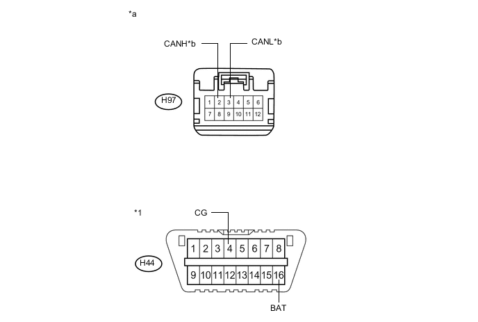
Standard Resistance Tester Connection Condition Specified Condition Purpose Connected to H97-2 (CANH) - H44-4 (CG) Cable disconnected from negative (-) auxiliary battery terminal 200 Ω or higher Inspection for CANH ground short CAN No. 1 junction connector H97-3 (CANL) - H44-4 (CG) Cable disconnected from negative (-) auxiliary battery terminal 200 Ω or higher Inspection for CANL ground short H97-2 (CANH) - H44-16 (BAT) Cable disconnected from negative (-) auxiliary battery terminal 6 kΩ or higher Inspection for CANH +B short H97-3 (CANL) - H44-16 (BAT) Cable disconnected from negative (-) auxiliary battery terminal 6 kΩ or higher Inspection for CANL +B short Text in Illustration *1 DLC3 - - *a Front view of wire harness connector
(to CAN No. 5 Junction Connector)
*b to CAN No. 1 Junction Connector Result Result Proceed to OK A NG (for LHD) B NG (for RHD) C Tech Tips
It is only necessary to perform the inspection in the above table for the result (short circuit) that was obtained in the Check Sub Bus 12 inspection.
A
REPLACE CAN NO. 5 JUNCTION CONNECTOR
C
CHECK FOR SHORT IN CAN BUS LINE (CAN NO. 5 J/C - CAN NO. 3 J/C) Click here
B
-
-
CHECK FOR SHORT IN CAN BUS LINE (CAN NO. 5 J/C - CAN NO. 1 J/C)
-
Disconnect the instrument panel wire from the CAN No. 1 junction connector.
-
Measure the resistance according to the value(s) in the table below.

Standard Resistance Tester Connection Condition Specified Condition Purpose Connected to H112-3 (CANH) - H44-4 (CG) Cable disconnected from negative (-) auxiliary battery terminal 200 Ω or higher Inspection for CANH ground short CAN No. 5 junction connector H112-9 (CANL) - H44-4 (CG) Cable disconnected from negative (-) auxiliary battery terminal 200 Ω or higher Inspection for CANL ground short H112-3 (CANH) - H44-16 (BAT) Cable disconnected from negative (-) auxiliary battery terminal 6 kΩ or higher Inspection for CANH +B short H112-9 (CANL) - H44-16 (BAT) Cable disconnected from negative (-) auxiliary battery terminal 6 kΩ or higher Inspection for CANL +B short Text in Illustration *1 DLC3 - - *a Front view of wire harness connector
(to CAN No. 1 Junction Connector)
*b to CAN No. 5 Junction Connector Tech Tips
It is only necessary to perform the inspection in the above table for the result (short circuit) that was obtained in the Check Sub Bus 12 inspection.
NG
REPAIR OR REPLACE CAN MAIN BUS LINE OR CONNECTOR (CAN NO. 1 J/C - CAN NO. 5 J/C)
OK
-
-
CHECK FOR SHORT IN CAN BUS LINE (CAN NO. 1 J/C)
-
Disconnect the engine room main wire from the CAN No. 1 junction connector.
-
Measure the resistance according to the value(s) in the table below.
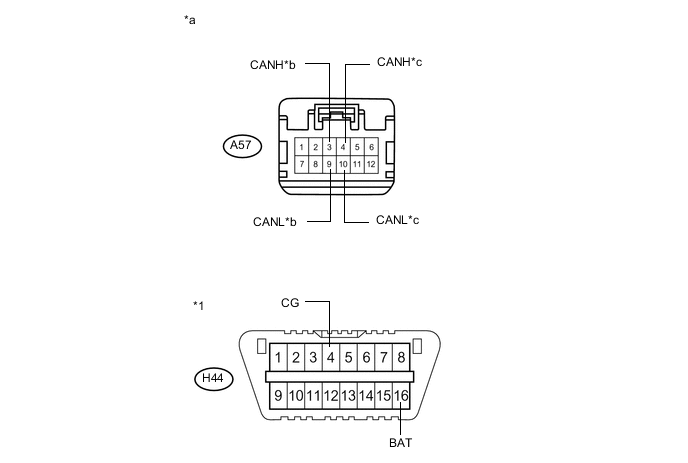
Standard Resistance Tester Connection Condition Specified Condition Purpose Connected to A57-3 (CANH) - H44-4 (CG) Cable disconnected from negative (-) auxiliary battery terminal 200 Ω or higher Inspection for CANH ground short Skid control ECU A57-9 (CANL) - H44-4 (CG) Cable disconnected from negative (-) auxiliary battery terminal 200 Ω or higher Inspection for CANL ground short A57-4 (CANH) - H44-4 (CG) Cable disconnected from negative (-) auxiliary battery terminal 200 Ω or higher Inspection for CANH ground short ECM A57-10 (CANL) - H44-4 (CG) Cable disconnected from negative (-) auxiliary battery terminal 200 Ω or higher Inspection for CANL ground short A57-3 (CANH) - H44-16 (BAT) Cable disconnected from negative (-) auxiliary battery terminal 6 kΩ or higher Inspection for CANH +B short Skid control ECU A57-9 (CANL) - H44-16 (BAT) Cable disconnected from negative (-) auxiliary battery terminal 6 kΩ or higher Inspection for CANL +B short A57-4 (CANH) - H44-16 (BAT) Cable disconnected from negative (-) auxiliary battery terminal 6 kΩ or higher Inspection for CANH +B short ECM A57-10 (CANL) - H44-16 (BAT) Cable disconnected from negative (-) auxiliary battery terminal 6 kΩ or higher Inspection for CANL +B short Tech Tips
It is only necessary to perform the inspection in the above table for the result (short circuit) that was obtained in the Check Sub Bus 12 inspection.
Text in Illustration *1 DLC3 - - *a Front view of wire harness connector
(to CAN No. 1 Junction Connector)
*b to Skid Control ECU *c to ECM - -
OK
REPLACE CAN NO. 1 JUNCTION CONNECTOR
B
-
-
CHECK CAN BUS LINE (ECU)
-
Disconnect the connector that includes terminals CANH and CANL from the ECU to which the bus line shorted to B+ or shorted to GND is connected.
-
Text in Illustration *a Component with harness connector
(Power Management Control ECU)
Measure the resistance according to the value(s) in the table below.
Standard Resistance Tester Connection Condition Specified Condition Purpose H4-31 (CA3P) - H4-4 (E12) Cable disconnected from negative (-) auxiliary battery terminal 200 Ω or higher Below 200 Ω:
CANH ground short
H4-30 (CA3N) - H4-4 (E12) Cable disconnected from negative (-) auxiliary battery terminal 200 Ω or higher Below 200 Ω:
CANL ground short
H4-31 (CA3P) - H4-7 (AM21) Cable disconnected from negative (-) auxiliary battery terminal 6 kΩ or higher Below 6 kΩ:
CANH +B short
H4-30 (CA3N) - H4-7 (AM21) Cable disconnected from negative (-) auxiliary battery terminal 6 kΩ or higher Below 6 kΩ:
CANL +B short
Tech Tips
It is only necessary to perform the inspection in the above table for the result (short circuit) that was obtained in the Check Sub Bus 12 inspection.
OK
REPLACE CORRESPONDING ECU
NG
REPAIR OR REPLACE CORRESPONDING ECU WIRE
-
-
CHECK FOR SHORT IN CAN BUS LINE (CAN NO. 5 J/C - CAN NO. 3 J/C)
-
Disconnect the instrument panel wire from the CAN No. 3 junction connector.
-
Measure the resistance according to the value(s) in the table below.
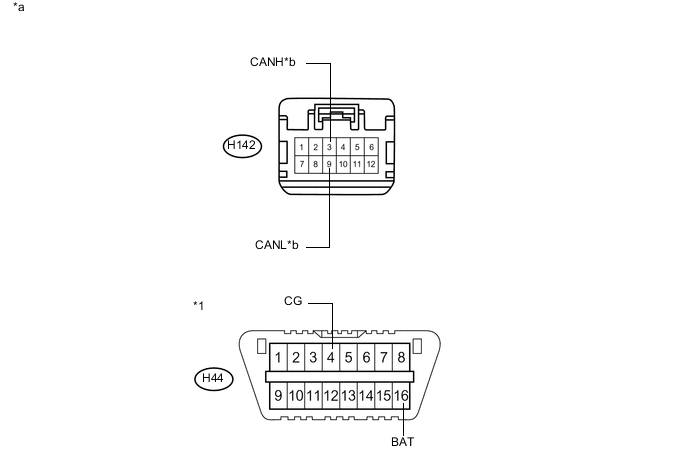
Standard Resistance Tester Connection Condition Specified Condition Purpose Connected to H142-3 (CANH) - H44-4 (CG) Cable disconnected from negative (-) auxiliary battery terminal 200 Ω or higher Inspection for CANH ground short CAN No. 5 junction connector H142-9 (CANL) - H44-4 (CG) Cable disconnected from negative (-) auxiliary battery terminal 200 Ω or higher Inspection for CANL ground short H142-3 (CANH) - H44-16 (BAT) Cable disconnected from negative (-) auxiliary battery terminal 6 kΩ or higher Inspection for CANH +B short H142-9 (CANL) - H44-16 (BAT) Cable disconnected from negative (-) auxiliary battery terminal 6 kΩ or higher Inspection for CANL +B short Text in Illustration *1 DLC3 - - *a Front view of wire harness connector
(to CAN No. 1 Junction Connector)
*b to CAN No. 5 Junction Connector Tech Tips
It is only necessary to perform the inspection in the above table for the result (short circuit) that was obtained in the Check Sub Bus 12 inspection.
NG
REPAIR OR REPLACE CAN MAIN BUS LINE OR CONNECTOR (CAN NO. 3 J/C - CAN NO. 5 J/C)
OK
-
-
CHECK FOR SHORT IN CAN BUS LINE (CAN NO. 3 J/C)
-
Disconnect the engine room main wire from the CAN No. 3 junction connector.
-
Measure the resistance according to the value(s) in the table below.
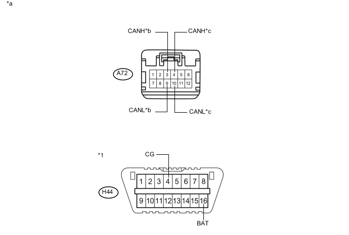
Standard Resistance Tester Connection Condition Specified Condition Purpose Connected to A72-3 (CANH) - H44-4 (CG) Cable disconnected from negative (-) auxiliary battery terminal 200 Ω or higher Inspection for CANH ground short Skid control ECU A72-9 (CANL) - H44-4 (CG) Cable disconnected from negative (-) auxiliary battery terminal 200 Ω or higher Inspection for CANL ground short A72-4 (CANH) - H44-4 (CG) Cable disconnected from negative (-) auxiliary battery terminal 200 Ω or higher Inspection for CANH ground short ECM A72-10 (CANL) - H44-4 (CG) Cable disconnected from negative (-) auxiliary battery terminal 200 Ω or higher Inspection for CANL ground short A72-3 (CANH) - H44-16 (BAT) Cable disconnected from negative (-) auxiliary battery terminal 6 kΩ or higher Inspection for CANH +B short Skid control ECU A72-9 (CANL) - H44-16 (BAT) Cable disconnected from negative (-) auxiliary battery terminal 6 kΩ or higher Inspection for CANL +B short A72-4 (CANH) - H44-16 (BAT) Cable disconnected from negative (-) auxiliary battery terminal 6 kΩ or higher Inspection for CANH +B short ECM A72-10 (CANL) - H44-16 (BAT) Cable disconnected from negative (-) auxiliary battery terminal 6 kΩ or higher Inspection for CANL +B short Tech Tips
It is only necessary to perform the inspection in the above table for the result (short circuit) that was obtained in the Check Sub Bus 12 inspection.
Text in Illustration *1 DLC3 - - *a Front view of wire harness connector
(to CAN No. 3 Junction Connector)
*b to Skid Control ECU *c to ECM - -
OK
REPLACE CAN NO. 3 JUNCTION CONNECTOR
NG
-
-
CHECK FOR SHORT IN CAN BUS LINE (ECU)
-
Disconnect the connector that includes terminals CANH and CANL from the ECU to which the bus line shorted to B+ or shorted to GND is connected.
-
Text in Illustration *a Component with harness connector
(Power Management Control ECU)
Measure the resistance according to the value(s) in the table below.
Standard Resistance Tester Connection Condition Specified Condition Purpose H4-31 (CA3P) - H4-4 (E12) Cable disconnected from negative (-) auxiliary battery terminal 200 Ω or higher Below 200 Ω:
CANH ground short
H4-30 (CA3N) - H4-4 (E12) Cable disconnected from negative (-) auxiliary battery terminal 200 Ω or higher Below 200 Ω:
CANL ground short
H4-31 (CA3P) - H4-7 (AM21) Cable disconnected from negative (-) auxiliary battery terminal 6 kΩ or higher Below 6 kΩ:
CANH +B short
H4-30 (CA3N) - H4-7 (AM21) Cable disconnected from negative (-) auxiliary battery terminal 6 kΩ or higher Below 6 kΩ:
CANL +B short
Tech Tips
It is only necessary to perform the inspection in the above table for the result (short circuit) that was obtained in the Check Sub Bus 12 inspection.
OK
REPLACE CORRESPONDING ECU
NG
REPAIR OR REPLACE CORRESPONDING ECU WIRE
-