CAN COMMUNICATION SYSTEM DIAGNOSIS SYSTEM
-
ECUS OR SENSORS WHICH COMMUNICATE THROUGH CAN COMMUNICATION SYSTEM
-
V1 Bus
-
ECM
-
Skid control ECU (brake booster with master cylinder assembly)
-
Main body ECU (multiplex network body ECU)
-
Yaw rate and acceleration sensor
-
Power steering ECU assembly
-
Certification ECU (smart key ECU assembly)
-
Airbag sensor assembly
-
Steering angle sensor (spiral cable with sensor sub-assembly)
-
Transmission control ECU assembly
-
Power management control ECU
-
Combination meter assembly
-
Radio receiver assembly*1*2
-
DCM (telematics transceiver)*3
-
-
V2 Bus
-
Power management control ECU
-
Driving support ECU assembly*4
-
Seat belt control ECU*4
-
Clearance warning ECU assembly*5
-
Rear television camera assembly*6
-
-
Power Management Bus
-
Power management control ECU
-
ECM
-
Skid control ECU (brake booster with master cylinder assembly)
-
Air conditioning amplifier assembly
-
-
CAN MS Bus*7
-
Main body ECU (multiplex network body ECU)
-
Position control ECU and switch assembly
-
Outer mirror control ECU assembly (driver side)
-
Outer mirror control ECU assembly (front passenger side)
-
-
Sensor Bus*4
-
Driving support ECU assembly
-
Millimeter wave radar sensor assembly
Tech Tips
*1: for Navigation Receiver Type
*2: for Radio and Display Type
*3: w/ Telematics Transceiver
*4: w/ Pre-crash Safety System
*5: w/ LEXUS Parking Assist-sensor System
*6: w/ Parking Assist Monitor System (w/o Parallel Parking Assist Function)
*7: w/ Seat Position Memory
-
-
-
CHECK FOR INSTALLED SYSTEMS (ECUS AND SENSORS) THAT ADOPT CAN COMMUNICATION
-
The systems (ECUs and sensors) that adopt CAN communication vary depending on the vehicle and optional equipment. Check which systems (ECUs and sensors) are installed to the vehicle.
ECU/Sensor Name GTS Display Applicability ECM ECM (Engine) Installed on all vehicles Power management control ECU
-
Hybrid Vehicle Control
-
Power Management1
Installed on all vehicles Transmission control ECU assembly Transmission Control Installed on all vehicles Combination meter assembly Combination Meter Installed on all vehicles Main body ECU (multiplex network body ECU) Main Body Installed on all vehicles Power steering ECU assembly Power Steering (EPS) Installed on all vehicles Skid control ECU (brake booster with master cylinder assembly) Skid Control (ABS/VSC/TRAC) Installed on all vehicles Steering angle sensor (spiral cable with sensor sub-assembly) Spiral cable (Steering Angle Sensor) Installed on all vehicles Yaw rate and acceleration sensor Yaw Rate Sensor Installed on all vehicles Airbag sensor assembly Airbag Installed on all vehicles Certification ECU (smart key ECU assembly) Certification (Smart) Installed on all vehicles Air conditioning amplifier assembly Air Conditioning Amplifier Installed on all vehicles Radio receiver assembly Display and Navigation (AVN1) Vehicles for navigation receiver type
Vehicles for radio and display type
DCM (telematics transceiver) DCM Vehicles with telematics transceiver Driving support ECU assembly Driving Support (Cruise Control-ACC) Vehicles with pre-crash safety system Clearance warning ECU assembly Clearance warning (Clearance Sonar1) Vehicles with LEXUS parking assist-sensor system Seat belt control ECU Seat Belt Control (Pre-crash) Vehicles with pre-crash safety system Position control ECU and switch assembly D-Seat Vehicles with seat position memory
-
Outer mirror control ECU assembly (driver side)*1
-
Outer mirror control ECU assembly (front passenger side)*2
Front Door LH/L-Mirror (FL-Door2/L-Miror) Vehicles with seat position memory
-
Outer mirror control ECU assembly (front passenger side)*1
-
Outer mirror control ECU assembly (driver side)*2
Front Door RH/R-Mirror (FR-Door2/R-Miror) Vehicles with seat position memory Rear television camera assembly Parking Assist Monitor System3 Vehicles with parking assist monitor system (w/o parallel parking assist function) Millimeter wave radar sensor assembly - Vehicles with pre-crash safety system
-
*1: for LHD
-
*2: for RHD
-
-
-
BUS CHECK (COMMUNICATION MALFUNCTION DTC)
Tech Tips
The ECUs and sensors that are properly connected to the CAN communication system can be displayed using the GTS.
-
Using the GTS, select the CAN Bus Check screen.
Note
-
It may be possible to select buses that do not have ECUs or sensors from the bus selection pull-down menu. This is not a malfunction. (This occurs when optional devices are not on a sub bus that is monitored by a gateway function equipped ECU.)
-
In the bus selection pull down menu, all buses applicable to the model are displayed (e.g. LIN communication buses are also displayed). Therefore, refer to the wiring diagrams to check the names of sub buses for CAN communication Click here.
Tech Tips
Different connection statuses are indicated by the background color of ECUs and sensors that are displayed.
Explanation of CAN Bus Check Screen Bus Type Background Color Connection Status V Bus White Communication has been normal since the start of the CAN bus check. Yellow Communication stop occurred at least once since the start of the CAN bus check, but communication is currently occurring (unstable communication). Red Communication was established at least once since the start of the CAN bus check, but communication is currently not occurring (unstable communication). Not displayed Communication stop has continued since the start of the CAN bus check.*1 Sub Bus
(gateway function equipped ECU that does not have history of connected ECUs)*2
White Communication has been normal since the start of the CAN bus check. Yellow Communication stop occurred at least once since the start of the CAN bus check, but communication is currently occurring (unstable communication). Red Communication was established at least once since the start of the CAN bus check, but communication is currently not occurring (unstable communication). Not displayed Communication stop has continued since the start of the CAN bus check.*1 Sub Bus
(gateway function equipped ECU that has history of connected ECUs)*3
White Communication has been normal since the start of the CAN bus check. Yellow Communication stop occurred at least once since the start of the CAN bus check, but communication is currently occurring (unstable communication). Red Currently not communicating (either of the following):
-
Communication stop has continued since the start of the CAN bus check.
-
Communication was established at least once since the start of the CAN bus check, but communication is currently not occurring.
Not displayed Either of the following:
-
If a gateway function equipped ECU cannot communicate, the sub bus and ECUs connected to the sub bus will not be displayed.
-
If no ECUs are connected to the sub bus, "There is no system found on the Communication Bus" will be displayed.
Tech Tips
-
Gateway function equipped ECUs relay signals between the ECUs connected to the different buses.
-
*1: ECUs that are present in the vehicle but are not displayed on the CAN Bus Check screen.
-
*2: Gateway function equipped ECU that does not memorize the sub bus ECUs that are connected to it.
-
*3: Gateway function equipped ECU that memorizes the sub bus ECUs that are connected to it.
-
If none of the connected ECUs are displayed, or there is no response from the vehicle to the GTS, check the DLC3 branch and the V bus main bus lines for a malfunction.
-
-
Observe the connection response screen for approximately 2 minutes to check for a change in connection status of the connected ECUs and sensors.
Tech Tips
-
If an open occurs in one of the lines of a CAN branch (except DLC3), output from the other branch line (the line that is not open) will be unstable and it may interfere with the response (display) of other ECUs and sensors.
-
If the connection status changes during the inspection, repair the open in the branch line of the ECU or sensor that does not respond (is not detected) and then perform the CAN bus check again.
-
-
-
HOW TO INTERPRET CAN BUS CHECK SCREEN
-
When a communication stop is currently occurring, the probable malfunctioning part can be determined from the CAN bus check and by using the following methods.
Note
The following CAN bus wiring diagram is provided only as an example. This wiring diagram is different from the actual wiring diagram for this vehicle.
Tech Tips
-
When a communication stop is currently occurring, it is easier to determine the probable malfunctioning part from the CAN bus check rather than from communication DTCs.
-
Wait for approximately 2 minutes after turning the power switch on (IG) (or simulate the driving conditions that enable the malfunction to be reproduced) and select "CAN Bus Check". Then observe the communication status of each ECU on the screen.
-
-
If a communication error of only 1 ECU or sensor is indicated on the CAN Bus Check screen, a communication stop of the ECU or sensor is suspected.
Example: Open in both CAN branch lines of ECU B on the V bus
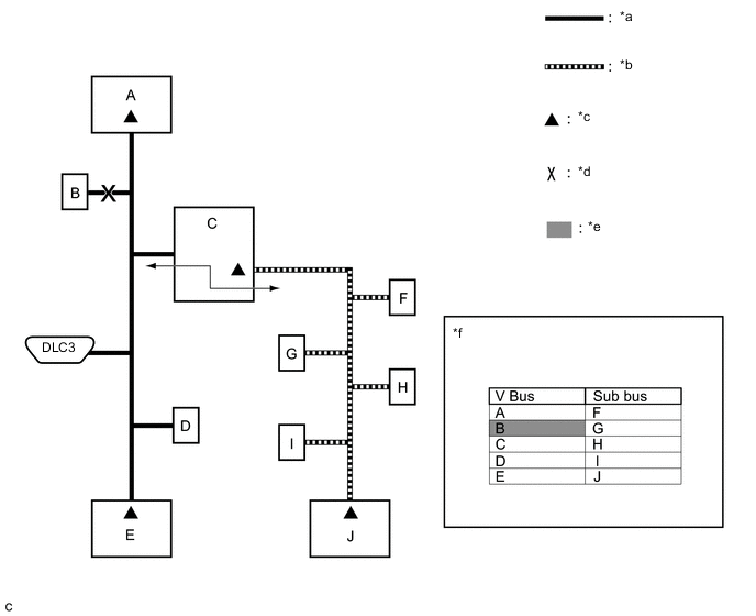
Text in Illustration *a V Bus *b Sub Bus *c Terminating Resistor *d Location of Malfunction *e Not displayed or background color changes to red or yellow *f CAN Bus Check Screen Tech Tips
When there are communication stops, ECUs are present in the vehicle even though they are not displayed on the CAN Bus Check screen.
-
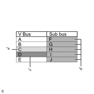
Text in Illustration *a Background color periodically changes to yellow or red *b Not displayed or background color is yellow or red *c Not displayed If communication errors for multiple ECUs or sensors are indicated on the CAN Bus Check screen, then a communication stop of the ECU or sensor that shows a more serious communication stop (an ECU or a sensor which is not displayed) is suspected.
Example: Open in a CAN branch line for ECU D on the V bus
Explanation of CAN Bus Check Screen Bus Type Background Color Connection Status V Bus White Communication has been normal since the start of the CAN bus check. Yellow Communication stop occurred at least once since the start of the CAN bus check, but communication is currently occurring (unstable communication). Red Communication was established at least once since the start of the CAN bus check, but communication is currently not occurring (unstable communication). Not displayed Communication stop has continued since the start of the CAN bus check.*1 Sub Bus
(gateway function equipped ECU that does not have history of connected ECUs)*2
White Communication has been normal since the start of the CAN bus check. Yellow Communication stop occurred at least once since the start of the CAN bus check, but communication is currently occurring (unstable communication). Red Communication was established at least once since the start of the CAN bus check, but communication is currently not occurring (unstable communication). Not displayed Communication stop has continued since the start of the CAN bus check.*1 Sub Bus
(gateway function equipped ECU that has history of connected ECUs)*3
White Communication has been normal since the start of the CAN bus check. Yellow Communication stop occurred at least once since the start of the CAN bus check, but communication is currently occurring (unstable communication). Red Currently not communicating (either of the following):
-
Communication stop has continued since the start of the CAN bus check.
-
Communication was established at least once since the start of the CAN bus check, but communication is currently not occurring.
Not displayed Either of the following:
-
If a gateway function equipped ECU cannot communicate, the sub bus and ECUs connected to the sub bus will not be displayed.
-
If no ECUs are connected to the sub bus, "There is no system found on the Communication Bus" will be displayed.
Tech Tips
-
Gateway function equipped ECUs relay signals between the ECUs connected to the different buses.
-
*1: ECUs that are present in the vehicle but are not displayed on the CAN Bus Check screen.
-
*2: Gateway function equipped ECU that does not memorize the sub bus ECUs that are connected to it.
-
*3: Gateway function equipped ECU that memorizes the sub bus ECUs that are connected to it.
-
The example of the CAN Bus Check screen in the illustration shows the result of electrical noise on the CAN bus which is caused by an open in a CAN branch line of ECU D (output from the other branch line is unstable) and the communication of ECU C is also unstable. In addition, in this example, ECU C is equipped with a gateway function. Therefore, communication is also unstable between the sub bus ECUs of ECU C and the V bus.
-
The example in the illustration shows that ECU D is not displayed on the CAN Bus Check screen. This indicates a more significant communication stop. In this case, a communication stop of ECU D is suspected.
-
-
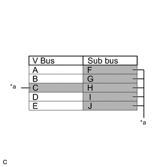
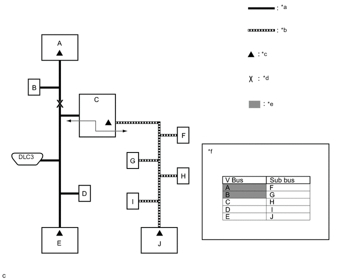
Text in Illustration *a Not displayed or background color changes to red If a communication error is indicated on both the V bus and sub bus on the CAN Bus Check screen, suspect any communication stop displayed for the V bus first.
Example: Open in both CAN branch lines of ECU C on the V bus
Tech Tips
-
In the CAN bus check, it is possible to confirm the communication status of ECUs connected to the V bus after connecting the GTS to the DLC3. As for sub buses, it is possible to confirm which sub bus connected ECUs can communicate with a gateway function equipped ECU on the V bus.
-
If a gateway function equipped ECU has a communication error, ECUs connected to the gateway function equipped ECU are also affected, and communication stops will be indicated.
-
The CAN Bus Check screen in the illustration shows that ECU C has a gateway function and a communication stop in ECU C is suspected.
-
-
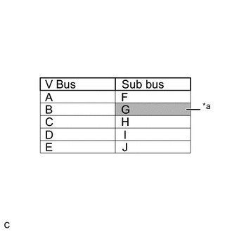
Text in Illustration *a Background color changes to red If the CAN Bus Check screen indicates a communication stop only in the sub bus, a communication stop in the sub bus is suspected.
Example: Open in both CAN branch lines of ECU G on the sub bus
Tech Tips
-
A communication error in a sub bus does not affect the V bus or other buses.
-
When a gateway function equipped ECU has memorized the ECUs that are connected to the sub bus, if any of the ECUs connected to the gateway function equipped ECU has a communication error, the background color changes to yellow or red. (The displayed name will not disappear.)
-
-
If both of the V bus main bus lines are open, ECUs or sensors that are located farther away from the DLC3 than the open part will be displayed as a communication stop on the CAN Bus Check screen.
(In this case, ECU A and B are not displayed or their background color changes to red.)
Text in Illustration *a V Bus *b Sub Bus *c Terminating Resistor *d Location of Malfunction *e Not displayed or background color is red *f CAN Bus Check Screen Tech Tips
If a communication error occurs in an ECU, it is not displayed on the CAN Bus Check screen even though the ECU is present.
-
If both of the sub bus main bus lines are open, ECUs that are located farther away from the gateway function equipped ECU than the open part will be displayed as a communication stop on the CAN Bus Check screen.
(In this case, ECU I and J are not displayed or their background color changes to red.)
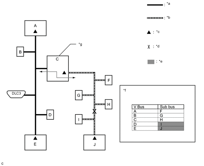
Text in Illustration *a V Bus *b Sub Bus *c Terminating Resistor *d Location of Malfunction *e Not displayed or background color is red *f CAN Bus Check Screen *g Gateway Function Equipped ECU - - -
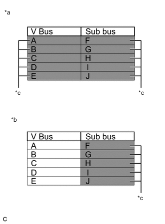
Text in Illustration *a When any of the following malfunctions occur on the V bus *b When any of the following malfunctions occur on a sub bus *c Not displayed When any of the following malfunctions occur, CAN communication cannot be established and almost all ECUs and sensors on the bus show a communication error on the CAN Bus Check screen.
Details of Malfunction Short between CAN lines (CANH and CANL) Short between a CAN line (CANH or CANL) and +B Short between a CAN line (CANH or CANL) and ground Open in a CAN main bus line Tech Tips
-
When a malfunction occurs on the V bus, almost all ECUs and sensors on the V bus and sub bus indicate a communication error (almost all ECUs are not displayed). As communication with the gateway function equipped ECU that is connected to the V bus stops, communication from the ECUs connected to the sub bus that is monitored by the gateway function equipped ECU also stops (these ECUs are not displayed).
-
When a malfunction occurs in a sub bus, almost all ECUs connected to the sub bus indicate a communication error.
-
A communication error in a sub bus does not affect the V bus or other buses.
-
The malfunctioning part can be determined by checking for a short circuit between CAN bus lines or between a CAN bus line and ground or +B short using an electrical tester.
-
-
-
HOW TO INTERPRET COMMUNICATION DTCS (DTCS THAT START WITH U)
-
If a CAN communication error cannot be reproduced, determine the suspected malfunctioning part using the DTCs stored in ECUs that are connected to the CAN buses by following the procedure below.
Tech Tips
Communication DTCs (DTCs that start with U) indicate a communication error between the ECU that stores the DTC and the ECU that is indicated by the DTC.
-
If multiple ECUs store a communication DTC for a particular ECU, a communication stop of the ECU is suspected.
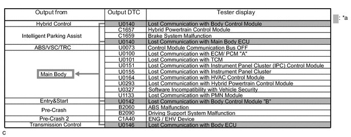
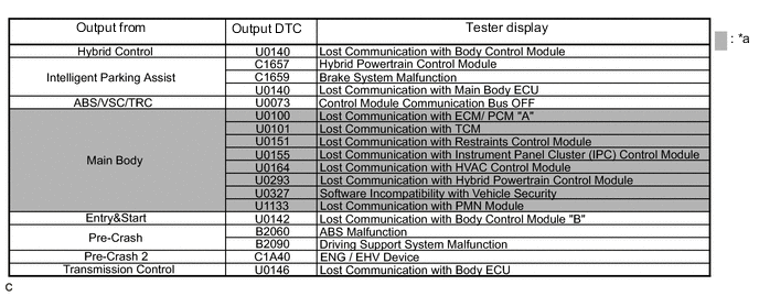
Text in Illustration *a Items to be Checked - - Note
-
This DTC table is from another model, and is only used here to show an example of DTCs that are output when there is an open in a CAN branch line for the main body ECU. This table does not show DTCs applicable to this vehicle.
-
Even though a DTC title may indicate a communication error with a specific ECU, the ECU name used in the DTC name on the GTS may differ depending on the ECU that stores the DTC. (Regarding output DTCs, refer to step 6 and the DTC chart for each ECU.)
Tech Tips
As multiple ECUs indicate a communication stop with the main body ECU, the possibility of a communication stop of the main body ECU is high.
-
-
If almost all of the communication DTCs of an ECU are stored, a communication stop of the ECU is suspected.
Text in Illustration *a Items to be Checked - - Note
This DTC table is from another model, and is only used here to show an example of DTCs that are output when there is an open in a CAN branch line for the main body ECU. This table does not show DTCs applicable to this vehicle.
Tech Tips
-
If almost all of the DTCs of the main body ECU are stored, the possibility of a communication stop of the main body ECU is high.
-
When a CAN communication error occurs, many DTCs are output. DTCs other than communication error DTCs (such as DTCs that start with C or B) and communication DTCs for the ABS system are important DTCs, however it may be easier to determine the malfunctioning part by examining the overall situation without considering these DTCs.
-
-
-
To help determine the part of the sub bus that has a communication error, prioritize the communication stop DTCs stored in the gateway function equipped ECU.
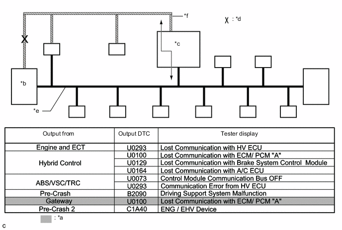
Text in Illustration *a Items to be Checked *b ECM *c Gateway Function Equipped ECU *d Location of Malfunction *e V Bus *f Sub Bus Note
This DTC table is from another model, and is only used here to show the ECUs connected to both a V bus and a sub bus. It shows DTCs output when there is an open in the main bus lines for the ECM on the sub bus. This table does not show DTCs applicable to this vehicle.
Tech Tips
-
As gateway function equipped ECUs (sub bus monitor ECU) monitor signals from all ECUs that are connected to sub buses, gateway function equipped ECUs can detect ECUs with a communication stop more accurately.
-
When there is a communication stop for the gateway function equipped ECU (gateway), communication with ECUs connected to other buses such as the V bus stops. Therefore, communication DTCs for ECUs connected to other buses are also stored.
-
-
When any of the following malfunctions occurs, many DTCs are likely to be output from many ECUs. Because of this, it may be difficult to determine the probable malfunctioning part.
-
Short between CAN lines (CANH and CANL)
-
Short between a CAN line (CANH or CANL) and ground
-
Short between a CAN line (CANH or CANL) and +B
-
Open in a CAN branch line (CANH or CANL) of an ECU or sensor
-
Open in a CAN main bus line (CANH or CANL) between 2 ECUs that have a terminating resistor
-
-
-
DTC TABLE BY ECU
Tech Tips
-
In the CAN communication system, the CAN communication DTCs of each ECU can be displayed using the GTS.
-
If CAN communication system DTCs are output, the malfunction cannot be determined only by the DTCs. Perform troubleshooting according to How to Proceed with Troubleshooting Click here.
-
If system function temporarily returns to normal, DTCs may not be output again even though the following DTC check procedures are used.
-
Power Management Control ECU / GTS Display "Hybrid Control"
DTC Code Detection Item U0100-211 Lost Communication with ECM/PCM "A" U0100-212 Lost Communication with ECM/PCM "A" U0100-530 Lost Communication with ECM/PCM "A" U0110-159*1 Lost Communication with Driver Motor Control Module U0110-160*2 Lost Communication with Driver Motor Control Module U0110-656*1 Lost Communication with Driver Motor Control Module U0110-657*1 Lost Communication with Driver Motor Control Module U0129-220 Lost Communication with Brake System Control Module U0129-222 Lost Communication with Brake System Control Module U0129-527 Lost Communication with Brake System Control Module U0129-528 Lost Communication with Brake System Control Module U0140-146 Lost Communication with Body Control Module U0151-763 Lost Communication with Airbag ECU U0164-594 Lost Communication with A/C ECU U0164-827 Lost Communication with A/C ECU U0424-537*3 Invalid Data Received from HVAC Control Module U1104-728*4 Lost Communication with Driving Support ECU U1107-436 Lost Communication with Power Management Module Tech Tips
-
This ECU uses the CAN communication system for DTC communication.
-
*1: Refer to Hybrid Control System Click here.
-
*2: Refer to Hybrid Control System Click here.
-
*3: Refer to Hybrid Control System Click here.
-
*4: Refer to Dynamic Radar Cruise Control System Click here.
-
-
Power Management Control ECU / GTS Display "Power Source Control"
DTC Code Detection Item U0129 Vehicle Speed Signal Communication U0293* HV ECU Communication Tech Tips
-
This ECU uses the CAN communication system for DTC communication.
-
*: Refer to Entry and Start System Click here.
-
-
Power Management Control ECU / GTS Display "PM1 Gateway"
DTC Code Detection Item U0104 Lost Communication with Driving Support ECU U0265 Lost Communication with Parking Assist Monitor Module U1002 Lost Communication with Gateway Module (Power Management1) U1100 Lost Communication with Seat Belt Control ECU U1110 Lost Communication with Clearance Sonar Module Tech Tips
-
This ECU uses the CAN communication system for DTC communication.
-
"PM1 Gateway" stores DTCs when a communication error is detected in the V2 bus.
-
-
Power Management Control ECU / GTS Display "PM2 Gateway"
DTC Code Detection Item U0100 Lost Communication with ECM/PCM U0129 Lost Communication with Brake System Control Module U0164 Lost Communication with A/C ECU U1002 Lost Communication with Gateway Module (Power Management2) Tech Tips
-
This ECU uses the CAN communication system for DTC communication.
-
"PM2 Gateway" stores DTCs when a communication error is detected in the power management bus.
-
-
Power Management Control ECU / GTS Display "Cruise Control"
DTC Code Detection Item U0122 Lost Communication with Vehicle Dynamic Control Module Tech Tips
This ECU uses the CAN communication system for DTC communication.
-
ECM / GTS Display "Engine and ECT"
DTC Code Detection Item U0293 Lost Communication with HV ECU Tech Tips
This ECU uses the CAN communication system for DTC communication.
-
Transmission Control ECU Assembly / GTS Display "ECT"
DTC Code Detection Item U0146 Lost Communication with Body ECU Tech Tips
This ECU uses the CAN communication system for DTC communication.
-
Power Steering ECU Assembly / GTS Display "EMPS"
DTC Code Detection Item U0129 Lost Communication with Brake System Control Module U0293 Lost Communication with HV ECU Tech Tips
This ECU uses the CAN communication system for DTC communication.
-
Skid Control ECU (Brake Booster with Master Cylinder Assembly) / GTS Display "ABS/VSC/TRC"
DTC Code Detection Item U0073 Control Module Communication Bus OFF U0123 Lost Communication with Yaw Rate Sensor Module U0124 Lost Communication with Lateral Acceleration Sensor Module U0126 Lost Communication with Steering Angle Sensor Module U0293 Communication Error from HV ECU Tech Tips
This ECU uses the CAN communication system for DTC communication.
-
Steering Angle Sensor (Spiral Cable with Sensor Sub-assembly) / - (GTS Display)
Tech Tips
The steering angle sensor (spiral cable with sensor sub-assembly) is connected to the CAN communication system, but the steering angle sensor (spiral cable with sensor sub-assembly) does not store or output CAN communication DTCs.
-
Yaw Rate and Acceleration Sensor / - (GTS Display)
Tech Tips
The yaw rate and acceleration sensor is connected to the CAN communication system, but the yaw rate and acceleration sensor does not store or output CAN communication DTCs.
-
Airbag Sensor Assembly / - (GTS Display)
Tech Tips
The airbag sensor assembly is connected to the CAN communication system, but the airbag sensor assembly does not store or output CAN communication DTCs.
-
Main Body ECU (Multiplex Network Body ECU) / GTS Display "Main Body"
DTC Code Detection Item U0100 Lost Communication with ECM/PCM "A" U0101 Lost Communication with TCM U0151 Lost Communication with Restraints Control Module U0155 Lost Communication with Instrument Panel Cluster U0163 Lost Communication with Navigation Control Module U0164 Lost Communication with HVAC Control Module U0199 Lost Communication with "Door Control Module A" U0200 Lost Communication with "Door Control Module B" U0208 Lost Communication with "Seat Control Module A" U0293 Lost Communication with Hybrid Powertrain Control Module U0327 Software Incompatibility with Vehicle Security U1002 Lost Communication with Gateway Module (Main body) U1133 Lost Communication with PMN Module Tech Tips
This ECU uses the CAN communication system for DTC communication.
-
Certification ECU (Smart Key ECU Assembly) / GTS Display "Entry&Start"
DTC Code Detection Item U0100 Lost Communication with ECM/PCM "A" U0142 Lost Communication with Body Control Module "B" U0155 Lost Communication with Instrument Panel Cluster (IPC) Control Module U0293 Lost Communication with HV ECU Tech Tips
This ECU uses the CAN communication system for DTC communication.
-
Air Conditioning Amplifier Assembly / GTS Display "Air Conditioner"
DTC Code Detection Item U0100 Lost Communication with ECM U0131 Lost Communication with Electric Power Steering ECU U0142 Lost Communication with Main Body ECU U0155 Lost Communication with Combination Meter U0293 Lost Communication with HV ECU Tech Tips
This ECU uses the CAN communication system for DTC communication.
-
Combination Meter Assembly / GTS Display "Combination Meter"
DTC Code Detection Item U0100 Lost Communication with ECM/PCM "A" U0103 Lost Communication with Gear Shift Module "A" U0129 Lost Communication with Skid Control ECU U0131 Lost Communication with Power Steering Control Module U0142 Lost Communication with Main Body ECU U0151 Lost Communication with Airbag ECU Tech Tips
This ECU uses the CAN communication system for DTC communication.
-
Radio Receiver Assembly (for Navigation Receiver Type) / GTS Display "Navigation System"
DTC Code Detection Item U0073 Sending Malfunction (Navigation to APGS) U0100 Engine ECU Communication U0126 Steering Sensor Communication U0129 VSC (ECB) ECU Communication U0140 Lost Communication with Body Control Module U0142 Lost Communication with Body Control Module "B" U0155 Meter ECU Communication U0163 Lost Communication with Navigation Control Module U0164 Air Conditioner ECU Communication U0198 Lost Communication with Telematic Control Module U0293 HV ECU Communication U1110 Clearance Sonar ECU Communication Tech Tips
This ECU uses the CAN communication system for DTC communication.
-
Radio Receiver Assembly (for Radio and Display Type) / GTS Display "Navigation System"
DTC Code Detection Item U0073 Sending Malfunction (Navigation to APGS) U0100 Lost Communication with ECM U0140 Lost Communication with Body Control Module U0155 Meter ECU Communication U0164 Air Conditioner ECU Communication U0293 HV ECU Communication U1110 Clearance Sonar ECU Communication Tech Tips
This ECU uses the CAN communication system for DTC communication.
-
Seat Belt Control ECU / GTS Display "Pre-Crash"
DTC Code Detection Item U0122 Lost Communication with Vehicle Dynamics Control Module U0140 Lost Communication with Main Body ECU U0151 Lost Communication with Airbag ECU U1104 Lost Communication with Driving Support ECU Tech Tips
This ECU uses the CAN communication system for DTC communication.
-
Driving Support ECU Assembly / GTS Display "Pre-Crash 2"
DTC Code Detection Item U0122 Lost Communication with Vehicle Dynamics Control Module U0123 Lost Communication with Yaw Rate Sensor Module U0126 Lost Communication with Steering Angle Sensor Module U0235*1 Lost Communication with Cruise Control Front Distance Range Sensor U0293 Lost Communication with HV ECU U1002 Lost Communication with Gateway Module (Sensor Bus) U1100 Lost Communication with Seat Belt Control ECU U1104*2 Lost Communication with Driving Support ECU Tech Tips
-
This ECU uses the CAN communication system for DTC communication.
-
*1: Refer to Pre-crash Safety System Click here.
-
*2: Refer to Pre-crash Safety System Click here.
-
-
Driving Support ECU Assembly / GTS Display "Radar Cruise"
DTC Code Detection Item U0122 Lost Communication with Vehicle Dynamics Control Module U0123 Lost Communication with Yaw Rate Sensor Module U0126 Lost Communication with Steering Angle Sensor Module U0235*1 Lost Communication with Cruise Control Front Distance Range Sensor U0293 Lost Communication with HV ECU U1104*2 Lost Communication with Driving Support ECU Tech Tips
-
This ECU uses the CAN communication system for DTC communication.
-
*1: Refer to Dynamic Radar Cruise Control System Click here.
-
*2: Refer to Dynamic Radar Cruise Control System Click here.
-
-
Clearance Warning ECU Assembly / GTS Display "Clearance Sonar"
DTC Code Detection Item U0101* Lost Communication with TCM U0155 Lost Communication with Instrument Panel Cluster Control Module (Combination Meter) Tech Tips
-
This ECU uses the CAN communication system for DTC communication.
-
*: Shift state signal cannot be received from power management control ECU.
-
-
Position Control ECU and Switch Assembly / - (GTS Display)
Tech Tips
The position control ECU and switch assembly is connected to the CAN communication system, but the position control ECU and switch assembly does not store or output CAN communication DTCs.
-
Outer Mirror Control ECU Assembly (Driver Side) / GTS Display "Mirror L" (for LHD), "Mirror R" (for RHD)
DTC Code Detection Item U0142 Lost Communication with Body Control Module "B" Tech Tips
This ECU uses the CAN communication system for DTC communication.
-
Outer Mirror Control ECU Assembly (Front Passenger Side) / GTS Display "Mirror R" (for LHD), "Mirror L" (for RHD)
DTC Code Detection Item U0142 Lost Communication with Body Control Module "B" Tech Tips
This ECU uses the CAN communication system for DTC communication.
-
Rear Television Camera Assembly / GTS Display "Advanced Parking Guidance/Parking Assist Monitor"
DTC Code Detection Item U0100 Lost Communication with ECM/PCM "A" U0126 Lost Communication with Steering Angle Sensor Module U0129 Lost Communication with Brake System Control Module U0140 Lost Communication with Body Control Module U0163 Lost Communication with Navigation Control Module U0293 Lost Communication with HV ECU U1000* CAN Communication Failure (Message Registry) U1110 Lost Communication with Intuitive Parking Assist Module Tech Tips
-
This ECU uses the CAN communication system for DTC communication.
-
*: The rear television camera assembly stores this DTC if an internal error related to the CAN communication system is detected Click here.
-
-
DCM (Telematics Transceiver) / - (GTS Display)
Tech Tips
-
This ECU uses the CAN communication system for DTC communication.
-
The DCM (telematics transceiver) informs the radio receiver assembly of output DTCs through the USB communication line.
-
-
Millimeter Wave Radar Sensor Assembly / - (GTS Display)
Tech Tips
The millimeter wave radar sensor assembly is connected to the CAN communication system, but the millimeter wave radar sensor assembly does not store or output CAN communication DTCs.
-
-
DTC COMBINATION TABLE
-
V1 Bus
DTC Trouble Mode Output ECU Output DTC Power Management Control ECU Communication Stop Mode ECM Communication Stop Mode Main Body ECU Communication Stop Mode Combination Meter ECU Communication Stop Mode Power Management Control ECU
(Hybrid Control)
U0100 ○*1 ○ X X U0129 ○*1 X X X U0140 ○*1 X ○ X U0151 ○*1 X X X U1107 ○*1 X X X Power Management Control ECU
(Electric Power Control)
U0129 ○*1 X X X U0293 ○*1 X X X Power Management Control ECU
(Cruise Control)
U0122 ○*1 X X X ECM U0293 X X X X Transmission Control ECU Assembly U0146 X X ○ X Main Body ECU (Multiplex Network Body ECU) U0100 X ○ ○*1 X U0101 ○ X ○*1 X U0151 X X ○*1 X U0155 X X ○*1 ○ U0163 X X ○*1 X U0164 ○ X ○*1 X U0293 ○ X ○*1 X U0327 X X ○*1 X U1133 ○ X ○*1 X Combination Meter Assembly U0100 ○ ○ X ○*1 U0103 X X X ○*1 U0129 X X X ○*1 U0131 X X X ○*1 U0142 X X ○ ○*1 U0151 X X X ○*1 Skid Control ECU (Brake Booster with Master Cylinder Assembly) U0073 X X X X U0123 X X X X U0124 X X X X U0126 X X X X U0293 ○ X X X Power Steering ECU Assembly U0129 X X X X U0293 ○ X X X Certification ECU (Smart Key ECU Assembly) U0100 X ○ X X U0142 X X ○ X U0155 X X X ○ U0293 ○ X X X Radio Receiver Assembly
(for Navigation Receiver Type)
U0073 X X X X U0100 ○ ○ X X U0126 X X X X U0129 X X X X U0140 X X ○ X U0142 X X ○ X U0155 X X X ○ U0163 X X X X U0164 ○ X X X U0198 X X X X U0293 ○ X X X U1110 ○ X X X Radio Receiver Assembly
(for Radio and Display Type)
U0073 X X X X U0100 ○ ○ X X U0140 X X ○ X U0155 X X X ○ U0164 ○ X X X U0293 ○ X X X U1110 ○ X X X DTC Trouble Mode Output ECU Output DTC Power Steering ECU Communication Stop Mode Skid Control ECU Communication Stop Mode Steering Angle Sensor Communication Stop Mode Yaw Rate Sensor Communication Stop Mode Power Management Control ECU
(Hybrid Control)
U0100 X X X X U0129 X ○ X X U0140 X X X X U0151 X X X X U1107 X X X X Power Management Control ECU
(Electric Power Control)
U0129 X ○ X X U0293 X X X X Power Management Control ECU
(Cruise Control)
U0122 X X X X ECM U0293 X X X X Transmission Control ECU Assembly U0146 X X X X Main Body ECU (Multiplex Network Body ECU) U0100 X X X X U0101 X X X X U0151 X X X X U0155 X X X X U0163 X X X X U0164 X X X X U0293 X X X X U0327 X X X X U1133 X X X X Combination Meter Assembly U0100 X X X X U0103 X X X X U0129 X ○ X X U0131 ○ X X X U0142 X X X X U0151 X X X X Skid Control ECU (Brake Booster with Master Cylinder Assembly) U0073 X ○*1, 2 ○ ○ U0123 X ○*1 X ○ U0124 X ○*1 X ○ U0126 X ○*1 ○ X U0293 X ○*1 X X Power Steering ECU Assembly U0129 ○*1 ○ X X U0293 ○*1 X X X Certification ECU (Smart Key ECU Assembly) U0100 X X X X U0142 X X X X U0155 X X X X U0293 X X X X Radio Receiver Assembly
(for Navigation Receiver Type)
U0073 X X X X U0100 X X X X U0126 X X ○ X U0129 X ○ X X U0140 X X X X U0142 X X X X U0155 X X X X U0163 X X X X U0164 X X X X U0198 X X X X U0293 X X X X U1110 X X X X Radio Receiver Assembly
(for Radio and Display Type)
U0073 X X X X U0100 X X X X U0140 X X X X U0155 X X X X U0164 X X X X U0293 X X X X U1110 X X X X DTC Trouble Mode Output ECU Output DTC Center Airbag Sensor Communication Stop Mode Certification ECU Communication Stop Mode Transmission Control ECU Communication Stop Mode Radio Receiver Assembly Communication Stop Mode DCM Communication Stop Mode Power Management Control ECU
(Hybrid Control)
U0100 X X X X X U0129 X X X X X U0140 X X X X X U0151 ○ X X X X U1107 X X X X X Power Management Control ECU
(Electric Power Control)
U0129 X X X X X U0293 X X X X X Power Management Control ECU
(Cruise Control)
U0122 X X X X X ECM U0293 X X X X X Transmission Control ECU Assembly U0146 X X ○*1 X X Main Body ECU (Multiplex Network Body ECU) U0100 X X X X X U0101 X X X X X U0151 ○ X X X X U0155 X X X X X U0163 X X X ○ X U0164 X X X X X U0293 X X X X X U0327 X ○ X X X U1133 X X X X X Combination Meter Assembly U0100 X X X X X U0103 X X ○ X X U0129 X X X X X U0131 X X X X X U0142 X X X X X U0151 ○ X X X X Skid Control ECU (Brake Booster with Master Cylinder Assembly) U0073 X X X X X U0123 X X X X X U0124 X X X X X U0126 X X X X X U0293 X X X X X Power Steering ECU Assembly U0129 X X X X X U0293 X X X X X Certification ECU (Smart Key ECU Assembly) U0100 X ○*1 X X X U0142 X ○*1 X X X U0155 X ○*1 X X X U0293 X ○*1 X X X Radio Receiver Assembly
(for Navigation Receiver Type)
U0073 X X X ○*1 X U0100 X X X ○*1 X U0126 X X X ○*1 X U0129 X X X ○*1 X U0140 X X X ○*1 X U0142 X X X X*1 ○ U0155 X X X ○*1 ○ U0163 X X X ○*1 ○ U0164 X X X ○*1 X U0198 X X X ○*1 ○ U0293 X X X ○*1 X U1110 X X X ○*1 X Radio Receiver Assembly
(for Radio and Display Type)
U0073 X X X ○*1 X U0100 X X X ○*1 X U0140 X X X ○*1 X U0155 X X X ○*1 X U0164 X X X ○*1 X U0293 X X X ○*1 X U1110 X X X ○*1 X Tech Tips
-
○: Set
-
X: Not set or may be set according to the malfunctioning part when one line of a branch is open.
-
*1: DTC is not output during communication error, but will be output as a history DTC (past DTC) when communication returns to normal.
-
*2: DTC U0123, U0124, U0126 and U0293 are not stored when DTC U0073 has already been stored.
-
Skid Control ECU Communication Stop Mode Click here
-
Power Steering ECU Communication Stop Mode Click here
-
Steering Angle Sensor Communication Stop Mode Click here
-
Yaw Rate Sensor Communication Stop Mode Click here
-
ECM Communication Stop Mode Click here
-
Transmission Control ECU Communication Stop Mode Click here
-
Main Body ECU Communication Stop Mode Click here
-
Combination Meter ECU Communication Stop Mode Click here
-
Center Airbag Sensor Communication Stop Mode Click here
-
Certification ECU Communication Stop Mode Click here
-
Power Management Control ECU Communication Stop Mode Click here
-
Radio Receiver Assembly Communication Stop Mode Click here
-
DCM Communication Stop Mode Click here
-
-