HYBRID VEHICLE TRANSAXLE INSTALLATION
PROCEDURE
-
INSTALL MOTOR CABLE
-
INSTALL GENERATOR CABLE
-
INSTALL MOTOR CABLE BRACKET
-
Install the motor cable bracket to the hybrid vehicle transaxle assembly with the bolt.
- Torque:
- 23 N*m { 235 kgf*cm, 17 ft.*lbf }
-
-
INSTALL WIRE HARNESS CLAMP BRACKET
-
Install the 2 wire harness clamp brackets to the hybrid vehicle transaxle assembly with the 2 bolts.
- Torque:
- 23 N*m { 235 kgf*cm, 17 ft.*lbf }
-
-
INSTALL REAR ENGINE MOUNTING BRACKET
-
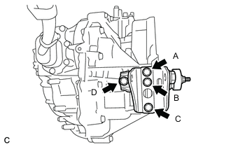
Install the rear engine mounting bracket to the hybrid vehicle transaxle assembly with the 4 bolts in several steps.
- Torque:
- 45 N*m { 459 kgf*cm, 33 ft.*lbf }
Note
Temporarily install bolt (A), and then fully install the 4 bolts in the order of (C), (B), (D) and (A).
-
-
INSTALL FRONT ENGINE MOUNTING BRACKET
-
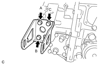
Install the front engine mounting bracket to the hybrid vehicle transaxle assembly with the 3 bolts in several steps.
- Torque:
- 64 N*m { 653 kgf*cm, 47 ft.*lbf }
Note
Temporarily install bolt (A), and then fully install the 3 bolts in the order of (B), (C) and (A).
-
-
SUPPORT HYBRID VEHICLE TRANSAXLE ASSEMBLY
-
Support the hybrid vehicle transaxle assembly with a transmission jack.
-
-
INSTALL HYBRID VEHICLE TRANSAXLE ASSEMBLY
-
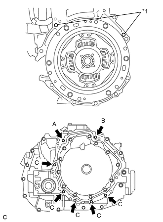
Text in Illustration *1 Knock Pin Make sure that the 2 knock pins are installed to the engine assembly.
-
Using a transmission jack, align the engine assembly and hybrid vehicle transaxle assembly, fit the knock pins into the knock pin holes, and install the 7 bolts shown in the illustration.
- Torque:
- 33 N*m { 337 kgf*cm, 24 ft.*lbf }
Note
-
Make sure to align the hybrid vehicle transaxle assembly so that the input shaft of the hybrid vehicle transaxle assembly will be inserted straight into the inner splines of the transmission input damper.
-
When inserting the input shaft of the hybrid vehicle transaxle assembly into the inner splines of the transmission input damper, do not shake the hybrid vehicle transaxle assembly excessively.
-
When mounting the hybrid vehicle transaxle assembly to the engine assembly, make sure to securely fit the knock pins into the knock holes.
-
Push in the hybrid vehicle transaxle assembly so that the contact surfaces of the engine assembly and hybrid vehicle transaxle assembly will be aligned evenly.
-
While mounting the hybrid vehicle transaxle assembly to the engine assembly, temporarily install the bolt (A), fully install the bolt (B), fully install the bolt (A), and then fully install the bolts (C).
-
Do not hang the hybrid vehicle transaxle assembly off of the engine assembly if the contact surfaces of the engine assembly and hybrid vehicle transaxle assembly are not in full contact. The knock holes of the hybrid vehicle transaxle case may be deformed due to the excessive weight of the engine assembly and hybrid vehicle transaxle assembly, resulting in misalignment between the engine assembly and hybrid vehicle transaxle assembly.
-
-
INSTALL ENGINE MOUNTING BRACKET LH
-
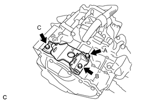
Install the engine mounting bracket LH to the hybrid vehicle transaxle assembly with 3 new bolts in several steps.
- Torque:
- 64 N*m { 653 kgf*cm, 47 ft.*lbf }
Note
Temporarily install bolt (A), and then fully install the 3 bolts in the order of (B), (C) and (A).
-
Install the engine mounting insulator LH to the engine mounting bracket LH with the through bolt and nut.
- Torque:
- 56 N*m { 571 kgf*cm, 41 ft.*lbf }
Note
When installing the engine mounting insulator LH, install the nut while holding the bolt.
-
-
INSTALL REAR ENGINE MOUNTING INSULATOR (for 2ZR-FXE)
-
INSTALL REAR ENGINE MOUNTING INSULATOR (for 5ZR-FXE)
-
INSTALL FRONT SUSPENSION CROSSMEMBER SUB-ASSEMBLY
-
TEMPORARILY INSTALL FRONT ENGINE MOUNTING INSULATOR (for 2ZR-FXE)
-
TEMPORARILY INSTALL FRONT ENGINE MOUNTING INSULATOR (for 5ZR-FXE)
-
INSTALL FRONT CROSSMEMBER SUB-ASSEMBLY
-
Install the front crossmember sub-assembly to the vehicle body with the 4 bolts.
- Torque:
- 99 N*m { 1010 kgf*cm, 73 ft.*lbf }
-
Install the front engine mounting insulator to the front crossmember sub-assembly with the 2 bolts.
- Torque:
- 95 N*m { 969 kgf*cm, 70 ft.*lbf }
-
Install the front engine mounting insulator with the bolt and nut.
- Torque:
- 145 N*m { 1479 kgf*cm, 107 ft.*lbf }
-
-
INSTALL FRONT SUSPENSION MEMBER REAR BRACE LH
-
INSTALL FRONT SUSPENSION MEMBER REAR BRACE RH
Tech Tips
Perform the same procedure as for the LH side.
-
INSTALL REAR SIDE RAIL REINFORCEMENT SUB-ASSEMBLY LH
-
INSTALL REAR SIDE RAIL REINFORCEMENT SUB-ASSEMBLY RH
Tech Tips
Perform the same procedure as for the LH side.
-
INSTALL FRONT ENGINE MOUNTING BRACKET LOWER REINFORCEMENT
-
INSTALL FLYWHEEL HOUSING SIDE COVER
-
Install the flywheel housing side cover to the engine assembly.
-
-
INSTALL STARTER HOLE INSULATOR
-
Install the starter hole insulator to the engine assembly with the 2 bolts.
- Torque:
- 37 N*m { 377 kgf*cm, 27 ft.*lbf }
-
-
REMOVE ENGINE HANGERS
-
Remove the 2 bolts and 2 engine hangers from the engine assembly.
-
-
INSTALL FRONT DRIVE SHAFT HOLE SNAP RING LH
-
INSTALL FRONT DRIVE SHAFT HOLE SNAP RING RH
Tech Tips
Perform the same procedure as for the LH side.
-
INSTALL FRONT DRIVE SHAFT ASSEMBLY LH
-
INSTALL FRONT DRIVE SHAFT ASSEMBLY RH
Tech Tips
Perform the same procedure as for the LH side.
-
CONNECT FRONT LOWER NO. 1 SUSPENSION ARM SUB-ASSEMBLY LH
-
CONNECT FRONT LOWER NO. 1 SUSPENSION ARM SUB-ASSEMBLY RH
Tech Tips
Perform the same procedure as for the LH side.
-
INSTALL FRONT STABILIZER LINK ASSEMBLY LH
-
INSTALL FRONT STABILIZER LINK ASSEMBLY RH
Tech Tips
Perform the same procedure as for the LH side.
-
CONNECT TIE ROD END SUB-ASSEMBLY LH
-
CONNECT TIE ROD END SUB-ASSEMBLY RH
Tech Tips
Perform the same procedure as for the LH side.
-
INSTALL FRONT SPEED SENSOR LH
-
INSTALL FRONT SPEED SENSOR RH
Tech Tips
Perform the same procedure as for the LH side.
-
INSTALL FRONT AXLE SHAFT NUT LH
-
INSTALL FRONT AXLE SHAFT NUT RH
Tech Tips
Perform the same procedure as for the LH side.
-
INSTALL FRONT EXHAUST PIPE ASSEMBLY (for 2ZR-FXE)
w/ Exhaust Heat Recirculation System Click here
w/o Exhaust Heat Recirculation System Click here
-
INSTALL FRONT EXHAUST PIPE ASSEMBLY (for 5ZR-FXE)
-
INSTALL FRONT CENTER FLOOR BRACE (for 2ZR-FXE)
-
INSTALL FRONT CENTER FLOOR BRACE (for 5ZR-FXE)
-
INSTALL FRONT NO. 3 ENGINE UNDER COVER (for 2ZR-FXE)
-
INSTALL FRONT NO. 3 ENGINE UNDER COVER (for 5ZR-FXE)
-
CONNECT NO. 1 STEERING COLUMN HOLE COVER SUB-ASSEMBLY
-
CONNECT NO. 2 STEERING INTERMEDIATE SHAFT ASSEMBLY
-
INSTALL COLUMN HOLE COVER SILENCER SHEET
-
INSTALL WIRE HARNESS
-
Engage the 12 clamps.
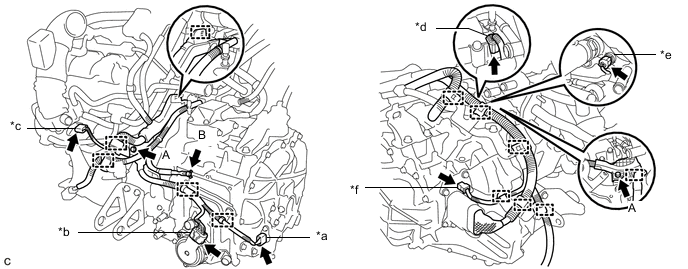
Text in Illustration *a Resolver Sensor Connector *b Shift Control Actuator Assembly Connector *c Throttle Body Assembly Connector *d Generator Cable Terminal Connector *e Engine Coolant Temperature Sensor Connector *f Motor Temperature Sensor Connector -
Install the 3 bolts.
- Torque:
- Bolt (A)
- 8.4 N*m { 86 kgf*cm, 74 in.*lbf }
- Bolt (B)
- 18 N*m { 184 kgf*cm, 13 ft.*lbf }
-
Connect the motor temperature sensor connector.
-
Connect the engine coolant temperature sensor connector.
-
Connect the generator cable terminal connector.
-
Connect the throttle body assembly connector.
-
Connect the shift control actuator assembly connector.
-
Connect the resolver sensor connector.
-
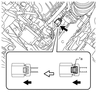
Text in Illustration *a Green-colored Lock Connect the electric inverter compressor connector and lock the green-colored lock as shown in the illustration.
CAUTION:
Wear insulated gloves when performing the procedure.
-
Install the earth wire to the engine assembly with the bolt.
-
Engage the 2 clamps.
-
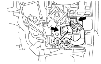
Connect the 2 engine room junction block connectors.
-
Engage the 2 claws.
-
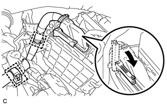
Connect the ECM connector with the lock lever.
-
Engage the 2 clamps.
-
-
CONNECT NO. 5 INVERTER COOLING HOSE (for 2ZR-FXE)
-
CONNECT NO. 5 INVERTER COOLING HOSE (for 5ZR-FXE)
-
CONNECT NO. 3 INVERTER COOLING HOSE (for 2ZR-FXE)
-
CONNECT NO. 3 INVERTER COOLING HOSE (for 5ZR-FXE)
-
INSTALL RADIATOR PIPE (for 2ZR-FXE)
-
INSTALL RADIATOR PIPE (for 5ZR-FXE)
-
CONNECT NO. 4 WATER BY-PASS HOSE (for 2ZR-FXE)
-
CONNECT NO. 4 WATER BY-PASS HOSE (for 5ZR-FXE)
-
CONNECT NO. 1 RADIATOR HOSE (for 2ZR-FXE)
-
CONNECT NO. 1 RADIATOR HOSE (for 5ZR-FXE)
-
INSTALL INVERTER TRAY BRACKET (for 2ZR-FXE)
-
INSTALL INVERTER TRAY BRACKET (for 5ZR-FXE)
-
INSTALL INVERTER RESERVE TANK ASSEMBLY (for 2ZR-FXE)
-
INSTALL INVERTER RESERVE TANK ASSEMBLY (for 5ZR-FXE)
-
INSTALL INVERTER WITH CONVERTER ASSEMBLY
-
CONNECT WATER HOSE
-
CONNECT NO. 2 ENGINE ROOM WIRE
-
REMOVE INVERTER COVER
-
CONNECT NO. 2 ENGINE WIRE
-
CONNECT MOTOR CABLE
-
CONNECT GENERATOR CABLE
-
CONNECT FRAME WIRE
-
CHECK HIGH VOLTAGE CABLE CONNECTION
-
INSTALL INVERTER COVER
-
CONNECT ENGINE ROOM MAIN WIRE
-
INSTALL NO. 1 INVERTER BRACKET
-
INSTALL AIR CLEANER HOSE ASSEMBLY (for 2ZR-FXE)
-
INSTALL AIR CLEANER HOSE ASSEMBLY (for 5ZR-FXE)
-
INSTALL AIR CLEANER CASE (for 2ZR-FXE)
-
INSTALL AIR CLEANER CASE (for 5ZR-FXE)
-
INSTALL INLET AIR CLEANER (for 2ZR-FXE)
-
INSTALL INLET AIR CLEANER (for 5ZR-FXE)
-
INSTALL WATER HOSE HOSE CLAMP (for 2ZR-FXE)
-
INSTALL WATER HOSE HOSE CLAMP (for 5ZR-FXE)
-
INSTALL AIR CLEANER CAP SUB-ASSEMBLY (for 2ZR-FXE)
-
INSTALL AIR CLEANER CAP SUB-ASSEMBLY (for 5ZR-FXE)
-
INSTALL SERVICE PLUG GRIP
-
CONNECT CABLE TO NEGATIVE AUXILIARY BATTERY TERMINAL
Note
When disconnecting the cable, some systems need to be initialized after the cable is reconnected Click here.
-
INSTALL REAR FLOOR BOARD UPPER NO. 3 PLATE
-
INSTALL DECK FLOOR BOX RH
-
INSTALL REAR NO. 3 FLOOR BOARD
-
INSTALL REAR DECK FLOOR BOX
-
INSTALL REAR NO. 2 FLOOR BOARD
-
ADD HYBRID TRANSAXLE FLUID
-
ADD COOLANT (for Inverter)
-
ADD COOLANT (for Engine)
for 2ZR-FXE Click here
for 5ZR-FXE Click here
-
INSPECT HYBRID TRANSAXLE FLUID
-
INSPECT FOR COOLANT LEAK (for Inverter)
-
INSPECT FOR COOLANT LEAK (for Engine)
for 2ZR-FXE Click here
for 5ZR-FXE Click here
-
INSPECT FOR EXHAUST GAS LEAK
-
INSTALL NO. 1 ENGINE UNDER COVER (for 2ZR-FXE)
-
INSTALL NO. 1 ENGINE UNDER COVER (for 5ZR-FXE)
-
INSTALL FRONT LOWER BUMPER ABSORBER (for 2ZR-FXE)
-
INSTALL FRONT LOWER BUMPER ABSORBER (for 5ZR-FXE)
-
INSTALL REAR ENGINE UNDER COVER LH (for 2ZR-FXE)
-
INSTALL REAR ENGINE UNDER COVER LH (for 5ZR-FXE)
-
INSTALL REAR ENGINE UNDER COVER RH (for 2ZR-FXE)
-
INSTALL REAR ENGINE UNDER COVER RH (for 5ZR-FXE)
-
INSTALL FRONT WHEEL (for 2ZR-FXE)
-
INSTALL FRONT WHEEL (for 5ZR-FXE)
-
INSTALL HOOD SUB-ASSEMBLY
-
Install the hood sub-assembly with the 4 bolts.
- Torque:
- 13 N*m { 133 kgf*cm, 10 ft.*lbf }
-
Engage the clamp.
-
Connect the washer hose.
-
-
INSPECT HOOD SUB-ASSEMBLY
-
ADJUST HOOD SUB-ASSEMBLY
-
INSTALL SUSPENSION TOWER DAMPER (w/ Suspension Tower Damper)
-
INSTALL OUTER COWL TOP PANEL SUB-ASSEMBLY (for LHD)
-
INSTALL OUTER COWL TOP PANEL SUB-ASSEMBLY (for RHD)
-
INSTALL COWL BODY MOUNTING REINFORCEMENT LH (for LHD)
-
INSTALL COWL BODY MOUNTING REINFORCEMENT RH (for RHD)
-
INSTALL NO. 2 HEATER AIR DUCT SPLASH SHIELD SEAL (for LHD)
-
INSTALL NO. 2 HEATER AIR DUCT SPLASH SHIELD SEAL (for RHD)
-
INSTALL NO. 1 HEATER AIR DUCT SPLASH SHIELD SEAL (for LHD)
-
INSTALL NO. 1 HEATER AIR DUCT SPLASH SHIELD SEAL (for RHD)
-
INSTALL WINDSHIELD WIPER MOTOR AND LINK ASSEMBLY
-
INSTALL NO. 2 CYLINDER HEAD COVER (for 2ZR-FXE)
-
INSTALL NO. 2 CYLINDER HEAD COVER (for 5ZR-FXE)
-
INSTALL RADIATOR SUPPORT OPENING COVER
-
INSTALL INVERTER COVER ASSEMBLY LH (w/ Cover)
-
INSPECT AND ADJUST FRONT WHEEL ALIGNMENT
-
CHECK ABS SPEED SENSOR SIGNAL