FRAME WIRE INSTALLATION
PROCEDURE
-
INSTALL FRAME WIRE
CAUTION:
Wear insulated gloves.
-
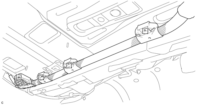
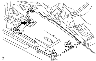
Install the frame wire with 4 new clamps.
-
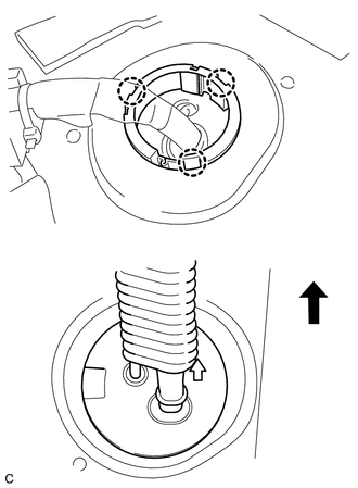
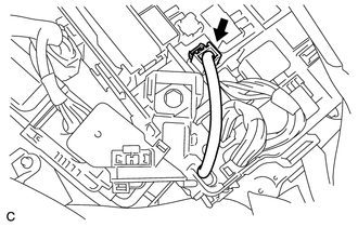
Insert the frame wire into the floor panel hole and engage the 3 claws.
Text in Illustration 
Front Side Tech Tips
The arrow should point toward the front of the vehicle.
-
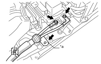
Install the nut.
- Torque:
- 8.4 N*m { 86 kgf*cm, 74 in.*lbf }
-
Engage the clamp.
-
Install the nut.
- Torque:
- 8.4 N*m { 86 kgf*cm, 74 in.*lbf }
-
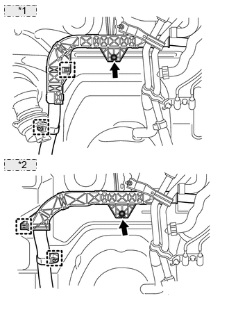
*1 for RHD: *2 for LHD: Engage the 2 clamps.
-
Install the nut.
- Torque:
- 8.4 N*m { 86 kgf*cm, 74 in.*lbf }
-
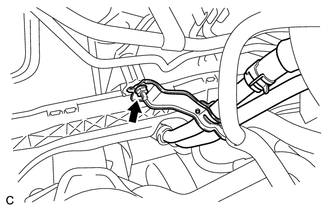
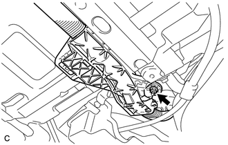
Install the heater water pipe sub-assembly with the nut.
- Torque:
- 9.8 N*m { 100 kgf*cm, 87 in.*lbf }
-
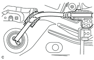
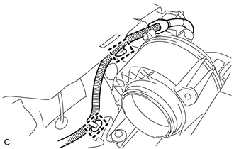
Engage the clamp.
-
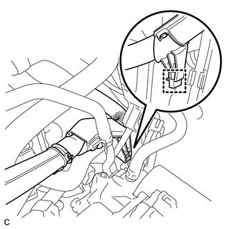
Engage the clamp.
-
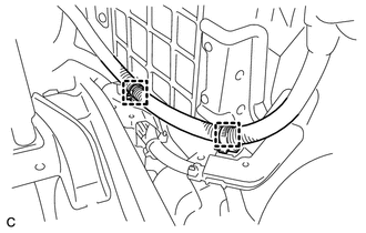
Engage the 2 clamps.
-
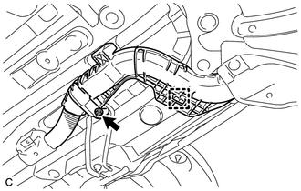
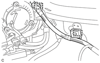
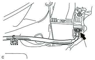
Connect the engine room junction block assembly connector.
-
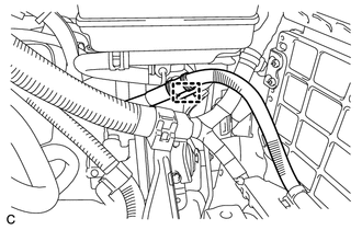
Engage the 2 clamps.
-
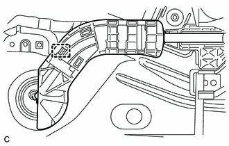
Engage the clamp to install the wire harness protector to the floor panel.
-
-
INSTALL INVERTER RESERVE TANK ASSEMBLY (for 2ZR-FXE)
-
INSTALL INVERTER RESERVE TANK ASSEMBLY (for 5ZR-FXE)
-
CONNECT HYBRID BATTERY JUNCTION BLOCK ASSEMBLY
CAUTION:
Wear insulated gloves.
-
Text in Illustration *a Earth Terminal Connect the frame wire to the hybrid battery junction block assembly with the 2 nuts.
- Torque:
- 9.0 N*m { 92 kgf*cm, 80 in.*lbf }
Note
-
Make sure that the ends of the frame wire are not crossed over each other.
-
Be sure to connect the ends of the frame wire to the connect terminals.
-
Connect the earth terminal.
-
Engage the clamp.
-
-
CHECK HIGH VOLTAGE CABLE CONNECTION CONDITION
-
CONNECT CABLE TO AUXILIARY BATTERY TERMINAL
-
Engage the 2 clamps.
-
Engage the 2 clamps.
-
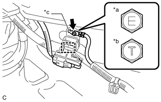
*a Type A *b Type B *c Earth Terminal Install the bolt to connect the earth terminal.
- Torque:
- Type A
- 8.4 N*m { 86 kgf*cm, 74 in.*lbf }
- Type B
- 10 N*m { 102 kgf*cm, 7 ft.*lbf }
-
Engage the clamp.
-
Connect the frame wire to the auxiliary battery terminal with the nut.
- Torque:
- 5.4 N*m { 55 kgf*cm, 48 in.*lbf }
-
Engage the clamp.
-
Install the terminal cover.
-
-
INSTALL UPPER HYBRID BATTERY COVER SUB-ASSEMBLY
-
INSTALL NO. 1 HYBRID BATTERY EXHAUST DUCT
-
INSTALL NO. 1 HYBRID BATTERY INTAKE DUCT
-
INSTALL REAR FLOOR BOARD SPACER
-
INSTALL HYBRID VEHICLE BATTERY SHIELD SHEET
-
INSTALL REAR NO. 1 FLOOR BOARD
-
INSTALL REAR NO. 2 FLOOR BOARD SUB-ASSEMBLY
-
INSTALL REAR NO. 1 FLOOR BOARD SUB-ASSEMBLY
-
INSTALL REAR SEAT SIDE GARNISH RH
-
INSTALL REAR DOOR SCUFF PLATE RH
-
INSTALL REAR SEATBACK ASSEMBLY RH
-
INSTALL FRONT SUSPENSION MEMBER BRACE REAR RH
-
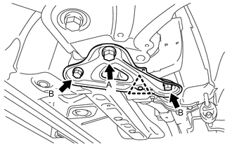
Install the front suspension member brace rear RH with a new bolt (A) and the 2 bolts (B).
- Torque:
- Bolt (A)
- 137 N*m { 1397 kgf*cm, 101 ft.*lbf }
- Bolt (B)
- 93 N*m { 948 kgf*cm, 69 ft.*lbf }
-
Install the clip.
-
-
INSTALL FRONT CENTER FLOOR COVER RH (w/ Cover)
-
Engage the 3 clips to install the front center floor cover RH.
-
-
INSTALL FRONT FLOOR COVER RH (w/ Cover)
-
Engage the 3 clips (B) to install the front floor cover RH.
-
Install the clip (A) and bolt.
-
-
INSTALL FRONT NO. 1 FLOOR HEAT INSULATOR
-
Install the front No. 1 floor heat insulator with the 3 nuts.
- Torque:
- 5.5 N*m { 56 kgf*cm, 49 in.*lbf }
-
-
INSTALL FRONT EXHAUST PIPE ASSEMBLY (for 2ZR-FXE)
-
INSTALL FRONT EXHAUST PIPE ASSEMBLY (for 5ZR-FXE)
-
INSTALL INVERTER WITH CONVERTER ASSEMBLY
-
INSTALL DECK FLOOR BOX LH (w/o Woofer)
-
INSTALL REAR NO. 4 FLOOR BOARD (w/ Woofer)
-
INSTALL REAR NO. 4 FLOOR BOARD (w/o Woofer)
-
INSTALL TONNEAU COVER ASSEMBLY (w/ Tonneau Cover)
-
INSTALL SERVICE PLUG GRIP