HYBRID BATTERY SYSTEM, Diagnostic DTC:P0A84-123
| DTC Code | DTC Name |
|---|---|
| P0A84-123 | Hybrid Battery Pack Cooling Fan 1 |
DESCRIPTION
-
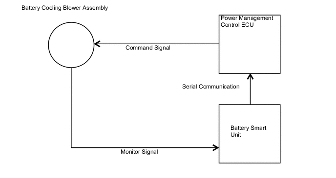
The speed of the battery cooling blower assembly is controlled by the power management control ECU. Battery cooling blower assembly power is supplied when the FCTL terminal of the power management control ECU turns on the battery blower relay. The power management control ECU sends command signals (SI) to the battery cooling blower assembly to get the fan speed corresponding to the HV battery temperature. Information about the voltage applied to the battery cooling blower assembly (VM) is sent to the power management control ECU as a monitor signal using serial communication via the battery smart unit.
| DTC No. | DTC Detection Condition | Trouble Area |
|---|---|---|
| P0A84-123 | When the output voltage of the battery cooling blower assembly (VM) is too low compared to the target control voltage range (1 trip detection) |
|
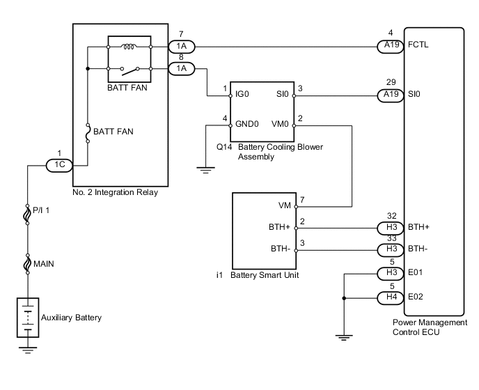
WIRING DIAGRAM
CAUTION / NOTICE / HINT
CAUTION:
-
Before inspecting the high-voltage system, take safety precautions to prevent electrical shocks, such as wearing insulated gloves and removing the service plug grip. After removing the service plug grip, put it in your pocket to prevent other technicians from accidentally reconnecting it while you are working on the high-voltage system.
-
After removing the service plug grip, wait for at least 10 minutes before touching any of the high-voltage connectors or terminals. After waiting for 10 minutes, check the voltage at the terminals in the inspection point in the inverter with converter assembly. The voltage should be 0 V before beginning work Click here.
Tech Tips
Waiting for at least 10 minutes is required to discharge the high-voltage capacitor inside the inverter with converter assembly.
Note
After turning the power switch off, waiting time may be required before disconnecting the cable from the negative (-) auxiliary battery terminal. Therefore, make sure to read the disconnecting the cable from the negative (-) auxiliary battery terminal notices before proceeding with work Click here.
PROCEDURE
-
CHECK DTC OUTPUT (HV)
-
Connect the intelligent tester to the DLC3.
-
Turn the power switch on (IG).
-
Enter the following menus: Powertrain / Hybrid Control / DTC.
-
Check if DTCs are output.
Result Result Proceed to P0AFC-123 is not output. A P0AFC-123 is also output. B -
Turn the power switch off.
B 
GO TO DTC CHART Click here
A 
-
-
PERFORM ACTIVE TEST USING INTELLIGENT TESTER
-
Connect the intelligent tester to the DLC3.
-
Turn the power switch on (IG).
-
Enter the following menus: Powertrain / Hybrid Control / Active Test / Driving the Battery Cooling Fan.
Note
If the Active Test cannot be performed, skip it and proceed to the next step to check fan operates and air is sucked. In accordance with fail-safe system operation, the power management control ECU sends a command to operate the battery cooling fan.
-
Select air volume mode 6 in the "Driving the Battery Cooling Fan" Active Test to operate the battery cooling blower assembly.
-
Check that the fan operates and air is sucked into the inlet duct.
Tech Tips
The cooling fan may not stop even when turning the cooling fan off in the "Driving the Battery Cooling Fan" Active Test. This is due to HV system control and not a malfunction.
OK The fan operates.
NG 
CHECK NO. 2 INTEGRATION RELAY (BATT FAN) Click here
OK
-
-
CHECK HARNESS AND CONNECTOR (BATTERY COOLING BLOWER - BATTERY SMART UNIT)
CAUTION:
Be sure to wear insulated gloves.
-
Check that the service plug grip is not installed.
Note
After removing the service plug grip, do not turn the power switch on (READY), unless instructed by the repair manual because this may cause a malfunction.
-
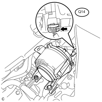
Disconnect connector Q14 from the battery cooling blower assembly.
-
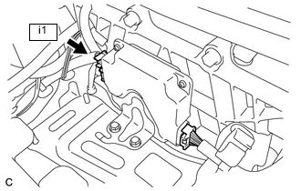
Disconnect connector i1 from the battery smart unit.
-
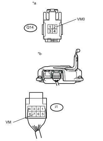
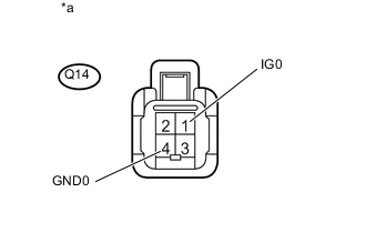
Text in Illustration *a Front view of wire harness connector
(to Battery Cooling Blower Assembly)
*b Rear view of wire harness connector
(to Battery Smart Unit)
Measure the resistance according to the value(s) in the table below.
Standard Resistance (Check for Open) Tester Connection Switch Condition Specified Condition Q14-2 (VM0) - i1-7 (VM) Power switch off Below 1 Ω Standard Resistance (Check for Short) Tester Connection Switch Condition Specified Condition Q14-2 (VM0) or i1-7 (VM) - Body ground Power switch off 10 kΩ or higher -
Connect the cable to the negative (-) auxiliary battery terminal.
-
Turn the power switch on (IG).
Note
-
After removing the service plug grip, do not turn the power switch on READY), unless instructed by the repair manual because this may cause a malfunction.
-
Turning the power switch on (IG) with the service plug grip removed causes an interlock switch system DTC to be set. Use the intelligent tester to clear the DTCs Click here.
-
-
Measure the voltage according to the value(s) in the table below.
Standard Voltage Tester Connection Switch Condition Specified Condition Q14-2 (VM0) - Body ground Power switch on (IG) Below 1 V Tech Tips
As there might be an intermittent malfunction, inspect the following items even if the measured voltage is as specified.
Check that each connector between the battery voltage sensor and battery cooling blower assembly is not loose or disconnected.
-
Turn the power switch off.
-
Disconnect the cable from the negative (-) auxiliary battery terminal.
-
Connect the battery cooling blower assembly connector.
-
Connect the battery smart unit connector.
NG
REPAIR OR REPLACE HARNESS OR CONNECTOR
OK
-
-
READ VALUE USING INTELLIGENT TESTER (VMF FAN MOTOR VOLTAGE)
CAUTION:
Be sure to wear insulated gloves.
-
Check that the service plug grip is not installed.
Note
After removing the service plug grip, do not turn the power switch on (READY), unless instructed by the repair manual because this may cause a malfunction.
-
Connect the cable to the negative (-) auxiliary battery terminal.
-
Connect the intelligent tester to the DLC3.
-
Turn the power switch on (IG).
Note
-
After removing the service plug grip, do not turn the power switch on READY), unless instructed by the repair manual because this may cause a malfunction.
-
Turning the power switch on (IG) with the service plug grip removed causes an interlock switch system DTC to be set. Use the intelligent tester to clear the DTCs Click here.
-
-
Enter the following menus: Powertrain / Hybrid Control / Trouble Codes.
-
Clear the DTCs and freeze frame data Click here.
-
Enter the following menus: Powertrain / Hybrid Control / Active Test / Driving the Battery Cooling Fan.
-
Enter the following menus: All Data / VMF Fan Motor Voltage 1.
-
Select each air volume mode (1 to 6) in the "Driving the Battery Cooling Fan" Active Test to operate the battery cooling blower assembly.
Note
If the Active Test cannot be performed, skip it and proceed to the next step to check fan operates and air is sucked. In accordance with fail-safe system operation, the power management control ECU sends a command to operate the battery cooling fan.
-
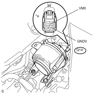
Text in Illustration *a Component with harness connected
(Battery Cooling Blower Assembly)
While the cooling fan is operating, compare the value in the Data List (VMF Fan Motor Voltage 1) with the frequency value that was actually measured at the battery cooling blower assembly connector.
Standard Tester Connection Condition Q14-2 (VM0) - Q14-4 (GND0) Battery cooling blower assembly is operating Tech Tips
Compare the values in each air volume mode (1 to 6). If the Active Test cannot be performed, compare the values only in the current air volume mode.
-
Turn the power switch off.
Result Result Proceed to The value in the Data List (VMF Fan Motor Voltage 1) and the actual measurement value at the battery cooling blower assembly connector are 0 V. A The value in the Data List (VMF Fan Motor Voltage 1) and the actual measurement value at the battery cooling blower assembly connector are not 0 V. B
B
CHECK BATTERY SMART UNIT (VOLTAGE) Click here
A
-
-
CHECK BATTERY SMART UNIT
CAUTION:
Be sure to wear insulated gloves.
-
Check that the service plug grip is not installed.
Note
After removing the service plug grip, do not turn the power switch on (READY), unless instructed by the repair manual because this may cause a malfunction.
-
Disconnect the connector i1 from the battery smart unit.
-
Connect the intelligent tester to the DLC3.
-
Connect the cable to the negative (-) auxiliary battery terminal.
-
Turn the power switch on (IG).
Note
-
After removing the service plug grip, do not turn the power switch on READY), unless instructed by the repair manual because this may cause a malfunction.
-
Turning the power switch on (IG) with the service plug grip removed causes an interlock switch system DTC to be set. Use the intelligent tester to clear the DTCs Click here.
-
-
Enter the following menus: Powertrain / Hybrid Control / Active Test / Driving the Battery Cooling Fan.
-
Select air volume mode 6 in the "Driving the Battery Cooling Fan" Active Test to operate the battery cooling blower assembly.
-
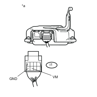
Text in Illustration *a Rear view of wire harness connector
(to Battery Smart Unit)
Measure the voltage according to the value(s) in the table below.
Standard Voltage Tester Connection Switch Condition Specified Condition i1-7 (VM) - i1-8 (GND) Power switch on (IG) during Active Test 1 V or more -
Turn the power switch off.
-
Connect the battery smart unit connector.
OK
REPLACE BATTERY SMART UNIT Click here
NG
REPLACE BATTERY COOLING BLOWER ASSEMBLY Click here
-
-
CHECK BATTERY SMART UNIT (VOLTAGE)
-
Check that the service plug grip is not installed.
Note
After removing the service plug grip, do not turn the power switch on (READY), unless instructed by the repair manual because this may cause a malfunction.
-
Connect the intelligent tester to the DLC3.
-
Turn the power switch on (IG).
Note
-
After removing the service plug grip, do not turn the power switch on (READY), unless instructed by the repair manual because this may cause a malfunction.
-
Turning the power switch on (IG) with the service plug grip removed causes an interlock switch system DTC to be set. Use the intelligent tester to clear the DTCs Click here.
-
-
Enter the following menus: Powertrain / Hybrid Control / Active Test / Driving the Battery Cooling Fan.
Note
If the Active Test cannot be performed, skip it and proceed to the next step to check voltage. In accordance with fail-safe system operation, the power management control ECU sends a command to operate the battery cooling fan.
-
Enter the following menus: All Data / VMF Fan Motor Voltage 1.
-
Select each air volume mode (1 to 6) in the "Driving the Battery Cooling Fan" Active Test to operate the battery cooling blower assembly.
-
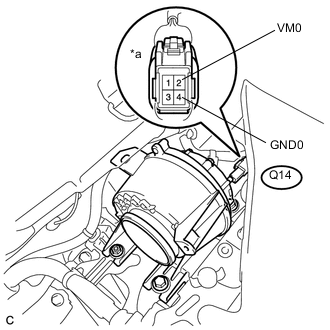
Text in Illustration *a Component with harness connected
(Battery Cooling Blower Assembly)
While the cooling fan is operating, compare the value in the data list (VMF Fan Motor Voltage 1) with the voltage value that was actually measured at the battery cooling blower assembly connector.
Standard Tester Connection Condition Specified Condition Q14-2 (VM0) - Q14-4 (GND0) Battery cooling blower is operating. Difference between the value in the Data List (VMF Fan Motor Voltage 1) and the actual measurement value is 1 V or less. Tech Tips
Compare the values in each air volume mode (1 to 6). If the active test cannot be performed, compare the values only in the current air volume mode.
OK
REPLACE BATTERY COOLING BLOWER ASSEMBLY Click here
NG
REPLACE BATTERY SMART UNIT Click here
-
-
CHECK NO. 2 INTEGRATION RELAY (BATT FAN)
-
Remove the No. 2 integration relay from the engine room junction block assembly Click here.
-
Measure the resistance according to the value(s) in the table below.
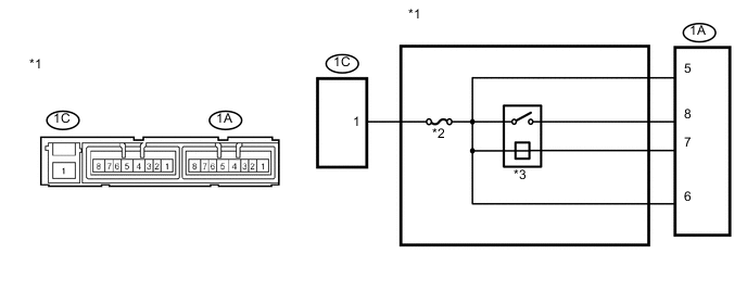
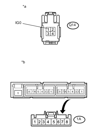
Text in Illustration *1 No. 2 Integration Relay *2 BATT FAN Fuse *3 BATT FAN Relay - - Standard Resistance Tester Connection Condition Specified Condition 1C-1 - 1A-8 Battery voltage is applied across terminals 1A-6 and 1A-7. Below 1 Ω No battery voltage is applied across terminals 1A-6 and 1A-7. 10 kΩ or higher -
Install the No. 2 integration relay Click here.
NG
REPLACE NO. 2 INTEGRATION RELAY Click here
OK
-
-
CHECK HARNESS AND CONNECTOR (NO. 2 INTEGRATION RELAY - BATTERY COOLING BLOWER ASSEMBLY) (VOLTAGE)
-
Check that the service plug grip is not installed.
Note
After removing the service plug grip, do not turn the power switch on (READY), unless instructed by the repair manual because this may cause a malfunction.
-
Connect the intelligent tester to the DLC3.
-
Turn the power switch on (IG).
Note
-
After removing the service plug grip, do not turn the power switch on READY), unless instructed by the repair manual because this may cause a malfunction.
-
Turning the power switch on (IG) with the service plug grip removed causes an interlock switch system DTC to be set. Use the intelligent tester to clear the DTCs Click here.
-
-
Enter the following menus: Powertrain / Hybrid Control / Trouble Codes.
-
Clear the DTCs and freeze frame data Click here.
-
*a Component with harness connected
(Battery Cooling Blower Assembly)
Measure the voltage according to the value(s) in the table below.
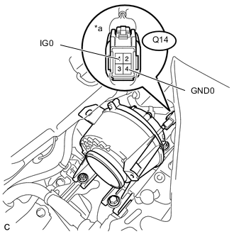
Standard Voltage Tester Connection Condition Specified Condition Q14-1 (IG0) - Q14-4 (GND0) Power switch on (IG) 11 to 14 V Text in Illustration *a Component with harness connected
(Battery Cooling Blower Assembly)
Tech Tips
Measure the voltage on the wire side of the connector that is part of the battery cooling blower assembly.
-
Turn the power switch off.
NG
CHECK HARNESS AND CONNECTOR (BATTERY COOLING BLOWER ASSEMBLY - BODY GROUND) Click here
OK
-
-
CHECK HARNESS AND CONNECTOR (BATTERY COOLING BLOWER - POWER MANAGEMENT CONTROL ECU)
-
Disconnect the cable from the negative (-) auxiliary battery terminal.
-
Check that the service plug grip is not installed.
Note
After removing the service plug grip, do not turn the power switch on (READY), unless instructed by the repair manual because this may cause a malfunction.
-
Disconnect connector Q14 from the battery cooling blower assembly.
-
Disconnect connector A19 from the power management control ECU Click here.
-
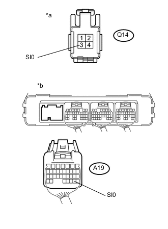
Text in Illustration *a Front view of wire harness connector
(to Battery Cooling Blower Assembly)
*b Rear view of wire harness connector
(to Power Management Control ECU)
Measure the resistance according to the value(s) in the table below.
Standard Resistance (Check for Open) Tester Connection Switch Condition Specified Condition Q14-3 (SI0) - A19-29 (SI0) Power switch off Below 1 Ω Standard Resistance (Check for Short) Tester Connection Switch Condition Specified Condition Q14-3 (SI0) or A19-29 (SI0) - Body ground Power switch off 10 kΩ or higher Note
When taking a measurement with a tester, do not apply excessive force to the tester probe to avoid damaging the holder.
-
Connect the cable to the negative (-) auxiliary battery terminal.
-
Turn the power switch on (IG).
Note
Turning the power switch on (IG) with the service plug grip removed causes an interlock switch system DTC to be set. Use the intelligent tester to clear the DTCs Click here.
-
Measure the voltage according to the value(s) in the table below.
Standard Voltage Tester Connection Switch Condition Specified Condition Q14-3 (SI0) - Body ground Power switch on (IG) Below 1 V -
Turn the power switch off.
-
Connect the battery cooling blower assembly connector.
-
Connect the power management control ECU connector Click here.
NG
REPAIR OR REPLACE HARNESS OR CONNECTOR
OK
-
-
CHECK POWER MANAGEMENT CONTROL ECU
-
Remove the power management control ECU.
-
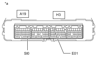
*a Component without harness connected
(Power Management Control ECU)
Measure the resistance according to the value(s) in the table below.
Standard Resistance Tester Connection Specified Condition A19-29 (SI0) - H3-5 (E01) 10 kΩ or higher -
Install the power management control ECU.
NG
REPLACE POWER MANAGEMENT CONTROL ECU Click here
OK
-
-
CHECK POWER MANAGEMENT CONTROL ECU (SI0 VOLTAGE)
-
Turn the power switch on (IG).
-
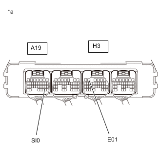
*a Component with harness connected
(Power Management Control ECU)
Measure the voltage according to the value(s) in the table below.
Standard Voltage Tester Connection Switch Condition Specified Condition A19-29 (SI0) - H3-5 (E01) Power switch on (IG) 4.5 to 5.5 V -
Turn the power switch off.
NG
REPLACE BATTERY COOLING BLOWER ASSEMBLY Click here
OK
-
-
CHECK BATTERY COOLING BLOWER ASSEMBLY
-
Check that the service plug grip is not installed.
Note
After removing the service plug grip, do not turn the power switch on (READY), unless instructed by the repair manual because this may cause a malfunction.
-
Connect the cable to the negative (-) auxiliary battery terminal.
-
Connect the intelligent tester to the DLC3.
-
Turn the power switch on (IG).
Note
-
After removing the service plug grip, do not turn the power switch on (READY), unless instructed by the repair manual because this may cause a malfunction.
-
If the power switch is turned on (IG) with the service plug grip removed, DTC P0A0D-350 for the interlock switch system will be stored. If this DTC is output, clear the DTC using the intelligent tester Click here.
-
-
Enter the following menus: Powertrain / Hybrid Control / Trouble Codes.
-
Clear the DTCs and freeze frame data Click here.
-
Enter the following menus: Powertrain / Hybrid Control / Active Test / Driving the Battery Cooling Fan.
-
Select each air volume mode (1 to 6) in the "Driving the Battery Cooling Fan" Active Test to operate the battery cooling blower assembly.
Note
If the Active Test cannot be performed, skip it and proceed to the next step to check the waveform. In accordance with fail-safe system operation, the power management control ECU sends a command to operate the battery cooling blower assembly.
-
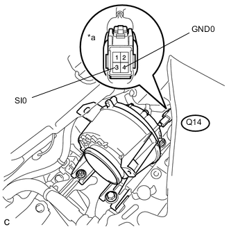
Text in Illustration *a Component with harness connected
(Battery Cooling Blower Assembly)
Connect an oscilloscope to the Q14 battery cooling blower assembly connector and check the waveform.
Item Content Tester Connection Q14-3 (SI0) - Q14-4 (GND0) Equipment Setting 10 V/DIV., 1 ms/DIV. Condition Power switch on (IG) during Active Test Note
Turning the power switch on (IG) with the service grip removed causes other DTCs to be stored. Clear the DTCs after performing this inspection.
Tech Tips
-
If DTCs are output after the check, clear the DTCs using the intelligent tester.
-
The frequency of the waveform will vary with the operating speed of the battery cooling blower assembly.
-
-
Turn the power switch off.
-
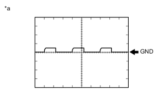
Text in Illustration *a Waveform 1 Disconnect the cable from the negative (-) auxiliary battery terminal.
Result Result Proceed to Normal (The pulse output of waveform 1) A No pulse generation B
A
REPLACE BATTERY COOLING BLOWER ASSEMBLY Click here
B
REPLACE POWER MANAGEMENT CONTROL ECU Click here
-
-
CHECK HARNESS AND CONNECTOR (BATTERY COOLING BLOWER ASSEMBLY - BODY GROUND)
-
Check that the service plug grip is not installed.
Note
After removing the service plug grip, do not turn the power switch on (READY), unless instructed by the repair manual because this may cause a malfunction.
-
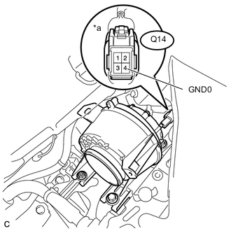
*a Component with harness connected
(Battery Cooling Blower Assembly)
Measure the resistance according to the value(s) in the table below.
Standard Resistance Tester Connection Condition Specified Condition Q14-4 (GND0) - Body ground Power switch off Below 1 Ω
NG
REPAIR OR REPLACE HARNESS OR CONNECTOR
OK
-
-
CHECK HARNESS AND CONNECTOR (NO. 2 INTEGRATION RELAY - POWER MANAGEMENT CONTROL ECU)
-
Disconnect connector A19 from the power management control ECU Click here.
-
Remove the No. 2 integration relay Click here.
-
Measure the resistance according to the value(s) in the table below.
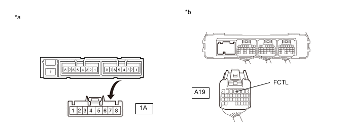
Standard Resistance Tester Connection Switch Condition Specified Condition 1A-7 - A19-4 (FCTL) Power switch off Below 1 Ω Text in Illustration *a Front view of wire harness connector
(to No. 2 Integration Relay)
*b Rear view of wire harness connector
(to Power Management Control ECU)
Note
When taking a measurement with a tester, do not apply excessive force to the tester probe to avoid damaging the holder.
-
Measure the voltage according to the value(s) in the table below.
Standard Voltage Tester Connection Switch Condition Specified Condition A19-4 (FCTL) - Body ground Power switch off Below 1 V Power switch on (IG) Below 1 V Note
If the power switch is turned on (IG) with the connector removed, DTCs will be stored. If the DTCs are output, clear the DTCs using the intelligent tester Click here.
-
Connect the power management control ECU connector Click here.
-
Install the No. 2 integration relay Click here.
NG
REPAIR OR REPLACE HARNESS OR CONNECTOR
OK
-
-
CHECK HARNESS AND CONNECTOR (POWER MANAGEMENT CONTROL ECU - BODY GROUND)
-
Disconnect the cable from the negative (-) auxiliary battery terminal.
-
Disconnect connector H3 from the power management control ECU Click here.
-
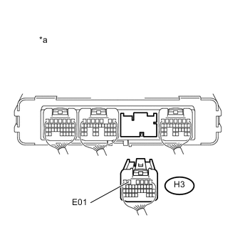
Text in Illustration *a Rear view of wire harness connector
(to Power Management Control ECU)
Measure the resistance according to the value(s) in the table below.
Standard Resistance Tester Connection Switch Condition Specified Condition H3-5 (E01) - Body ground Power switch off Below 1 Ω Note
When taking a measurement with a tester, do not apply excessive force to the tester probe to avoid damaging the holder.
-
Connect the power management control ECU connector Click here.
-
Connect the cable to the negative (-) auxiliary battery terminal.
NG
REPAIR OR REPLACE HARNESS OR CONNECTOR
OK
-
-
CHECK HARNESS AND CONNECTOR (POWER MANAGEMENT CONTROL ECU - BODY GROUND)
-
Disconnect the cable from the negative (-) auxiliary battery terminal.
-
Disconnect connector H4 from the power management control ECU Click here.
-
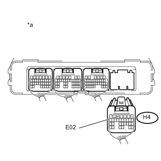
Text in Illustration *a Rear view of wire harness connector
(to Power Management Control ECU)
Measure the resistance according to the value(s) in the table below.
Standard Resistance Tester Connection Switch Condition Specified Condition H4-5 (E02) - Body ground Power switch off Below 1 Ω Note
When taking a measurement with a tester, do not apply excessive force to the tester probe to avoid damaging the holder.
-
Connect the power management control ECU connector Click here.
-
Connect the cable to the negative (-) auxiliary battery terminal.
NG
REPAIR OR REPLACE HARNESS OR CONNECTOR
OK
-
-
CHECK HARNESS AND CONNECTOR (NO. 2 INTEGRATION RELAY - BATTERY COOLING BLOWER ASSEMBLY)
-
Disconnect the cable from the negative (-) auxiliary battery terminal.
-
Remove the No. 2 integration relay Click here.
-
Disconnect connector Q14 from the battery cooling blower assembly.
-
Text in Illustration *a Front view of wire harness connector
(to Battery Cooling Blower Assembly)
*b Front view of wire harness connector
(to No. 2 Integration Relay)
Measure the resistance according to the value(s) in the table below.
Standard Resistance Tester Connection Switch Condition Specified Condition 1A-8 - Q14-1 (IG0) Power switch off Below 1 Ω -
Install the No. 2 integration relay Click here.
-
Connect the battery cooling blower assembly connector.
-
Connect the cable to the negative (-) auxiliary battery terminal.
OK
REPLACE POWER MANAGEMENT CONTROL ECU Click here
NG
REPAIR OR REPLACE HARNESS OR CONNECTOR
-
-
REPLACE NO. 2 INTEGRATION RELAY
-
Replace the No. 2 integration relay Click here.
NEXT
-
-
CHECK HARNESS AND CONNECTOR (NO. 2 INTEGRATION RELAY - BATTERY COOLING BLOWER ASSEMBLY)
-
Disconnect the cable from the negative (-) auxiliary battery terminal.
-
Remove the No. 2 integration relay Click here.
-
Disconnect connector Q14 from the battery cooling blower assembly.
-
Text in Illustration *a Front view of wire harness connector
(to Battery Cooling Blower Assembly)
*b Front view of wire harness connector
(to No. 2 Integration Relay)
Measure the resistance according to the value(s) in the table below.
Standard Resistance Tester Connection Switch Condition Specified Condition Q14-1 (IG0) - Terminals other than 1A-8 and body ground Power switch off 10 kΩ or higher -
Install the No. 2 integration relay Click here.
-
Connect the battery cooling blower assembly connector.
-
Connect the cable to the negative (-) auxiliary battery terminal.
NG
REPAIR OR REPLACE HARNESS OR CONNECTOR
OK
-
-
CHECK BATTERY COOLING BLOWER ASSEMBLY
CAUTION:
Be sure to wear insulated gloves.
-
Disconnect connector Q14 from the battery cooling blower assembly.
-
Text in Illustration *a Component without harness connected
(Battery Cooling Blower Assembly)
Measure the resistance according to the value(s) in the table below.
Standard Resistance Tester Connection Switch Condition Specified Condition Q14-1 (IG0) - Q14-4 (GND0) and body ground Power switch off 10 kΩ or higher -
Connect the battery cooling blower assembly connector.
OK
END
NG
REPLACE BATTERY COOLING BLOWER ASSEMBLY Click here
-