AUDIO AND VISUAL SYSTEM(for Radio and Display Type) Stereo Jack Adapter Light does not Illuminate
DESCRIPTION
Power is supplied to the No. 1 stereo jack adapter assembly illumination from the radio receiver assembly.
WIRING DIAGRAM
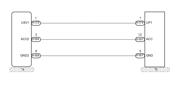
| *a | Radio Receiver Assembly |
| *b | No. 1 Stereo Jack Adapter Assembly |
PROCEDURE
-
CHECK HARNESS AND CONNECTOR (NO. 1 STEREO JACK ADAPTER ASSEMBLY ILLUMINATION POWER SOURCE)
-
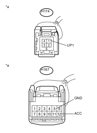
Text in Illustration *a Front view of wire harness connector
(to No. 1 Stereo Jack Adapter Assembly)
Disconnect the H167 and H174 No. 1 stereo jack adapter assembly connectors.
-
Measure the voltage according to the value(s) in the table below.
Standard Voltage Tester Connection Condition Specified Condition H174-1 (UP1) - Body ground Power switch on (ACC) 5 V H167-12 (ACC) - H167-5 (GND) Power switch on (ACC) 11 to 14 V
OK 
REPLACE NO. 1 STEREO JACK ADAPTER ASSEMBLY Click here
NG 
-
-
CHECK HARNESS AND CONNECTOR (RADIO RECEIVER ASSEMBLY - NO. 1 STEREO JACK ADAPTER ASSEMBLY)
-
Disconnect the H175 radio receiver assembly connector.
-
Disconnect the H174 No. 1 stereo jack adapter assembly connector.
-
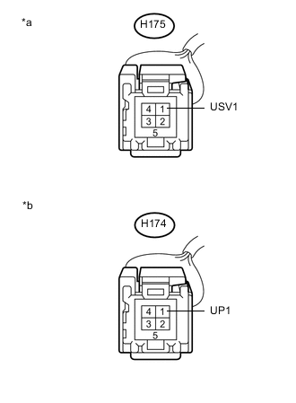
Text in Illustration *a Front view of wire harness connector
(to Radio Receiver Assembly)
*b Front view of wire harness connector
(to No. 1 Stereo Jack Adapter Assembly)
Measure the resistance according to the value(s) in the table below.
Standard Resistance Tester Connection Condition Specified Condition H174-1 (UP1) - H175-1 (USV1) Always Below 1 Ω H174-1 (UP1) - Body ground Always 10 kΩ or higher
NG
REPAIR OR REPLACE HARNESS OR CONNECTOR
OK
-
-
CHECK HARNESS AND CONNECTOR (RADIO RECEIVER ASSEMBLY - NO. 1 STEREO JACK ADAPTER ASSEMBLY)
-
Disconnect the H169 radio receiver assembly connector.
-
Disconnect the H167 No. 1 stereo jack adapter assembly connector.
-
Measure the resistance according to the value(s) in the table below.
Standard Resistance Tester Connection Condition Specified Condition H169-3 (ACC2) - H167-12 (ACC) Always Below 1 Ω H169-8 (GND2) - H167-5 (GND) Always Below 1 Ω H169-3 (ACC2) - Body ground Always 10 kΩ or higher H169-8 (GND2) - Body ground Always 10 kΩ or higher
OK
REPLACE RADIO RECEIVER ASSEMBLY Click here
NG
REPAIR OR REPLACE HARNESS OR CONNECTOR
-