AUDIO AND VISUAL SYSTEM(for Radio and Display Type), Diagnostic DTC:B15C0, B15C1
| DTC Code | DTC Name |
|---|---|
| B15C0 | GPS Antenna Connection Malfunction(short) |
| B15C1 | GPS Antenna Connection Malfunction(break) |
DESCRIPTION
These DTCs are stored when a malfunction occurs in the navigation antenna assembly.
| DTC No. | Detection Item | DTC Detection Condition | Trouble Area |
|---|---|---|---|
| B15C0 | GPS Antenna Connection Malfunction(short) | Navigation antenna assembly error |
|
| B15C1 | GPS Antenna Connection Malfunction(break) | Navigation antenna assembly power source malfunction |
|
-
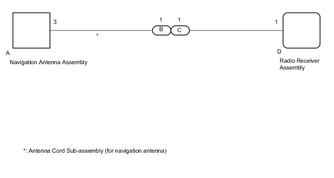
*: for LHD
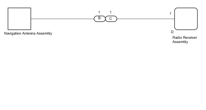
WIRING DIAGRAM
-
for LHD
-
for RHD
CAUTION / NOTICE / HINT
Note
Check that the navigation antenna assembly cable is properly installed and does not have any sharp bends, pinching or loose connections before performing the following inspection procedure.
PROCEDURE
-
CHECK DTC
-
Clear the DTCs.
-
Recheck for DTCs and check that no DTCs are output.
OK No DTCs are output. Result Result Proceed to OK A NG (for RHD) B NG (for LHD) C
A 
USE SIMULATION METHOD TO CHECK Click here
C 
CHECK HARNESS AND CONNECTOR (ANTENNA CORD SUB-ASSEMBLY (for Navigation Antenna) - RADIO RECEIVER ASSEMBLY) Click here
B 
-
-
CHECK HARNESS AND CONNECTOR (NAVIGATION ANTENNA ASSEMBLY - RADIO RECEIVER ASSEMBLY)
-
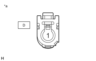
*a Front view of wire harness connector
(to Radio Receiver Assembly)
Disconnect the radio receiver assembly connector.
-
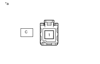
*a Front view of wire harness connector
(to Navigation Antenna Assembly)
Disconnect the navigation antenna assembly connector.
-
Measure the resistance according to the value(s) in the table below.
Tester Connection Condition Specified Condition D-1 - C-1 Always Below 1 Ω D-1 or C-1- Body ground Always 10 kΩ or higher Result Proceed to OK NG
NG
REPAIR OR REPLACE HARNESS OR CONNECTOR
OK
-
-
INSPECT NAVIGATION ANTENNA ASSEMBLY
-
Remove the navigation antenna assembly.
-
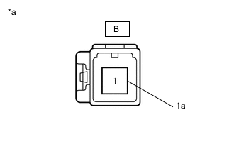
*a Component without harness connected
(Navigation Antenna Assembly)
Measure the resistance according to the value(s) in the table below.
Tester Connection Condition Specified Condition B-1 - B-1a Always 50 to 500 Ω Result Proceed to OK NG
OK
REPLACE RADIO RECEIVER ASSEMBLY Click here
NG
REPLACE NAVIGATION ANTENNA ASSEMBLY Click here
-
-
CHECK HARNESS AND CONNECTOR (ANTENNA CORD SUB-ASSEMBLY (for Navigation Antenna) - RADIO RECEIVER ASSEMBLY)
-

*a Front view of wire harness connector
(to Radio Receiver Assembly)
Disconnect the radio receiver assembly connector.
-

*a Front view of wire harness connector
(to Antenna Cord Sub-assembly (for Navigation Antenna))
Disconnect the antenna cord sub-assembly (for navigation antenna) connector.
-
Measure the resistance according to the value(s) in the table below.
Tester Connection Condition Specified Condition D-1 - C-1 Always Below 1 Ω D-1 or C-1- Body ground Always 10 kΩ or higher Result Proceed to OK NG
NG
REPAIR OR REPLACE HARNESS OR CONNECTOR
OK
-
-
INSPECT ANTENNA CORD SUB-ASSEMBLY (for Navigation Antenna)
-
Remove the antenna cord sub-assembly (for navigation antenna).
-
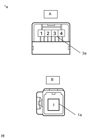
*a Component without harness connected
(Antenna Cord Sub-assembly ((for Navigation Antenna)))
Measure the resistance according to the value(s) in the table below.
Standard Resistance Tester Connection Condition Specified Condition A-3 - B-1 Always Below 1 Ω A-3a - B-1a Always Below 1 Ω A-3 or B-1 - Body ground Always 10 kΩ or higher Result Proceed to OK NG
NG
REPLACE ANTENNA CORD SUB-ASSEMBLY (for Navigation Antenna) Click here
OK
-
-
INSPECT NAVIGATION ANTENNA ASSEMBLY
-
Remove the navigation antenna assembly.
-
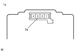
*a Component without harness connected
(Navigation Antenna Assembly)
Measure the resistance according to the value(s) in the table below.
Standard Resistance Tester Connection Condition Specified Condition 3 - 3a Always 50 to 500 Ω Result Proceed to OK NG
OK
REPLACE RADIO RECEIVER ASSEMBLY Click here
NG
REPLACE NAVIGATION ANTENNA ASSEMBLY Click here
-