SLIDING ROOF HOUSING INSTALLATION
PROCEDURE
-
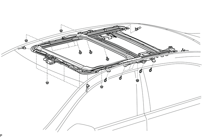
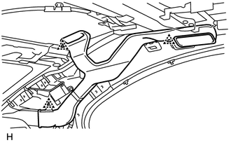
INSTALL SLIDING ROOF HOUSING SUB-ASSEMBLY
-
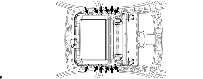
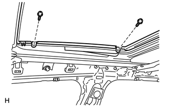
Temporarily install the sliding roof housing sub-assembly with the 12 bolts (vehicle body side) and 8 nuts.
-
Tighten the 8 nuts.
- Torque:
- 5.5 N*m { 56 kgf*cm, 49 in.*lbf }
-
Tighten the 12 bolts.
- Torque:
- 8.0 N*m { 82 kgf*cm, 71 in.*lbf }
-
Tighten the 12 bolts.
- Torque:
- 5.4 N*m { 55 kgf*cm, 48 in.*lbf }
-
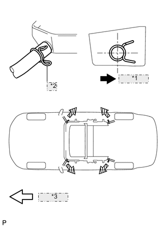
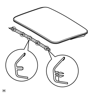
*1 Outer Side *2 Clip *3 Front Side Connect the 4 drain hoses.
Note
The clip must face toward the outside of the vehicle and also be above the lower surface of the sliding roof housing when installing the drain hoses.
-
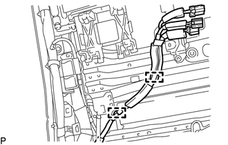
w/ Rear Seat Entertainment System:
Attach the 2 clamps to connect the wire harness.
-
-
INSTALL REAR SLIDING ROOF HOUSING MOUNTING BRACKET LH
-
Install the rear sliding roof housing mounting bracket LH with the 2 bolts.
- Torque:
- 8.0 N*m { 82 kgf*cm, 71 in.*lbf }
-
Attach the clamp to connect the curtain shield airbag wire harness.
-
-
INSTALL REAR SLIDING ROOF HOUSING MOUNTING BRACKET RH
Tech Tips
Use the same procedure described for the LH side.
-
INSTALL SLIDING ROOF PANEL PLATE
-
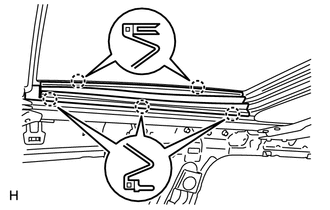
Attach the 2 guides to install the 2 sliding roof panel plates with the 4 bolts.
-
-
INSTALL FRONT SLIDING ROOF GARNISH
-
Attach the 5 claws to install the front sliding roof garnish.
-
-
INSTALL SLIDING ROOF GLASS SUB-ASSEMBLY
-
Using a T25 "TORX" driver, temporarily install the sliding roof glass sub-assembly with the 4 screws.
-
Perform a level check.
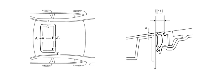
*1 Even
-
Check the difference in the level for "a" between the roof panel and the upper surface of the weatherstrip when the sliding roof glass sub-assembly is fully closed.
Standard Area Measurement A - A -2.0 to +1.0 mm (-0.079 to +0.039 in.) B - B -1.0 to +2.0 mm (-0.039 to +0.079 in.) C - C -1.5 to +1.5 mm (-0.059 to +0.059 in.) D - D -1.0 to +1.5 mm (-0.039 to +0.059 in.) Tech Tips
"+" represents the condition that the glass is above the panel level. "-" represents the condition that the glass is below the panel level.
-
Perform a gap check.
Check the gap between the roof panel and roof glass.
Note
The gap must be even all around.
-
-
Using a T25 "TORX" driver, tighten the 4 screws.
- Torque:
- 5.5 N*m { 56 kgf*cm, 49 in.*lbf }
-
-
CHECK FOR WATER LEAKS
-
After adjusting the sliding roof glass sub-assembly, check for water leaks.
-
If there are any leaks, readjust the sliding roof glass sub-assembly.
-
-
INSTALL SLIDING ROOF SIDE GARNISH LH
-
Attach the 5 claws to install the sliding roof side garnish LH.
-
-
INSTALL SLIDING ROOF SIDE GARNISH RH
Tech Tips
Use the same procedure described for the LH side.
-
INSTALL NO. 1 ROOF SIDE AIR DUCT LH (w/ Rear Cooler)
-
Install the No. 1 roof side air duct LH with the 3 clips.
-
-
INSTALL NO. 1 ROOF SIDE AIR DUCT RH (w/ Rear Cooler)
Tech Tips
Use the same procedure described for the LH side.
-
INSTALL CURTAIN SHIELD AIRBAG ASSEMBLY LH
-
INSTALL CURTAIN SHIELD AIRBAG ASSEMBLY RH
Tech Tips
Use the same procedure described for the LH side.
-
INSTALL ROOF HEADLINING ASSEMBLY (for Long Body)
-
INSTALL ROOF HEADLINING ASSEMBLY (for Standard Body)
-
CONNECT CABLE TO NEGATIVE BATTERY TERMINAL
Note
When disconnecting the cable, some systems need to be initialized after the cable is reconnected Click here.
-
INSTALL COWL TOP VENTILATOR LOUVER RH
-
CHECK SRS WARNING LIGHT