INSTRUMENT PANEL SAFETY PAD INSTALLATION
CAUTION / NOTICE / HINT
Tech Tips
-
Use the same procedure for RHD and LHD vehicles.
-
The procedure listed below is for LHD vehicles.
-
A bolt without a torque specification is shown in the standard bolt chart Click here.
PROCEDURE
-
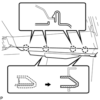
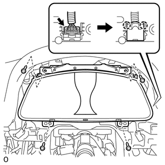
INSTALL NO. 3 INSTRUMENT PANEL STAY
-
Attach the 5 claws to install the 5 No. 3 instrument panel stays.
-
-
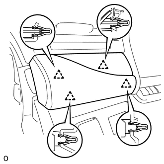
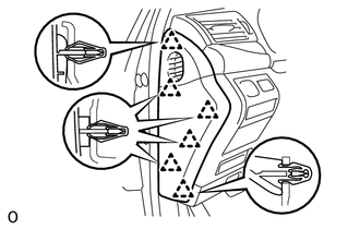
INSTALL INSTRUMENT PANEL SAFETY PAD SUB-ASSEMBLY
-
Attach the 5 clips to install the instrument panel safety pad sub-assembly.
-
Install the 2 bolts <E>.
- Torque:
- 20 N*m { 204 kgf*cm, 15 ft.*lbf }
-
Install the 8 bolts <A> and nut <F>.
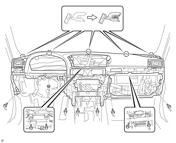
*1 Bolt <A> *2 Bolt <E> *3 Nut <F> - - -
Attach the 2 claws to connect the cooler thermistor.
-
Connect each connector and each wire harness clamp.
-
-
INSTALL TIRE PRESSURE MONITOR RECEIVER ASSEMBLY (w/ Tire Pressure Warning System)
-
INSTALL TELEMATICS TRANSCEIVER (w/ Telematics Transceiver)
-
INSTALL FRONT NO. 3 SPEAKER ASSEMBLY
-
INSTALL NO. 1 SPEAKER HOLE COVER
-
INSTALL FRONT NO. 2 SPEAKER ASSEMBLY
-
INSTALL NO. 1 INSTRUMENT PANEL SPEAKER PANEL SUB-ASSEMBLY
-
INSTALL NO. 2 INSTRUMENT PANEL SPEAKER PANEL SUB-ASSEMBLY
-
INSTALL FRONT PILLAR GARNISH LH
-
INSTALL FRONT PILLAR GARNISH RH
-
INSTALL ACCESSORY METER ASSEMBLY
-
INSTALL INSTRUMENT PANEL FINISH PANEL SUB-ASSEMBLY
-
Attach the 10 clips to install the instrument panel finish panel sub-assembly.
-
-
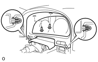
INSTALL GLOVE COMPARTMENT DOOR ASSEMBLY
-
Connect each connector and each wire harness clamp.
-
Install the glove compartment door assembly with the 5 screws <C>.
-
-
INSTALL FRONT PASSENGER SIDE KNEE AIRBAG ASSEMBLY
-
INSTALL LOWER INSTRUMENT PANEL
-
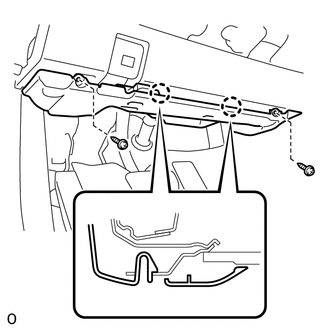
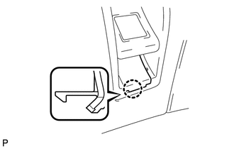
INSTALL NO. 2 INSTRUMENT PANEL UNDER COVER SUB-ASSEMBLY
-
Connect the connector.
-
Insert the 2 guides.
-
Attach the 4 claws to install the No. 2 instrument panel under cover sub-assembly.
-
-
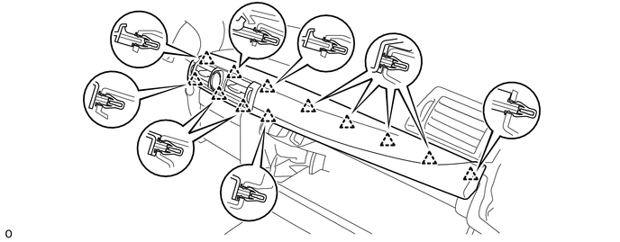
INSTALL INSTRUMENT CLUSTER FINISH PANEL GARNISH ASSEMBLY
-
Connect each connector.
-
Attach the 12 clips to install the instrument cluster finish panel garnish assembly.
-
-
INSTALL MULTI-MEDIA MODULE RECEIVER ASSEMBLY
-
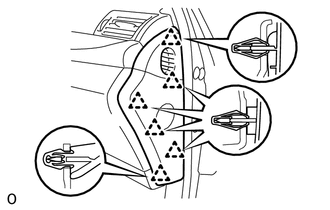
INSTALL INSTRUMENT SIDE PANEL RH
-
Attach the 6 clips to install the instrument side panel RH.
-
-
INSTALL CONSOLE BOX ASSEMBLY
-
w/o Rear Seat Entertainment System:
-
for 5-Passenger with Ottoman:
-
w/ Disc Player:
-
-
INSTALL COMBINATION METER ASSEMBLY
-
Connect the connector and attach the 2 claws to close the connector cover.
-
Install the combination meter assembly with the 4 screws.
-
-
INSTALL NO. 2 INSTRUMENT CLUSTER FINISH PANEL SUB-ASSEMBLY
-
Connect the 2 connectors.
-
Attach the 2 clips to install the No. 2 instrument cluster finish panel sub-assembly.
-
Install the 2 clips.
-
-
INSTALL HEADLIGHT DIMMER SWITCH ASSEMBLY
-
INSTALL DRIVER SIDE KNEE AIRBAG ASSEMBLY
-
INSTALL NO. 1 INSTRUMENT PANEL UNDER COVER SUB-ASSEMBLY
-
Connect each connector and each wire harness clamp.
-
Attach the 2 claws to connect the DLC3.
-
Attach the 2 claws to install the No. 1 instrument panel under cover sub-assembly.
-
Install the 2 screws.
-
-
INSTALL NO. 1 INSTRUMENT PANEL SAFETY PAD SUB-ASSEMBLY
-
Connect each connector.
-
Attach the 5 clips and claw to install the No. 1 instrument panel safety pad sub-assembly.
-
Install the screw <C> and bolt.
-
Attach the claw to install the switch base hole cover to the No. 1 instrument panel safety pad sub-assembly.
-
-
INSTALL INSTRUMENT PANEL ORNAMENT
-
Connect the connector.
-
Attach the 4 clips to install the instrument panel ornament.
-
-
INSTALL INSTRUMENT SIDE PANEL LH
-
Attach the 6 clips to install the instrument side panel LH.
-
-
CONNECT CABLE TO NEGATIVE BATTERY TERMINAL
Note
When disconnecting the cable, some systems need to be initialized after the cable is reconnected.
-
ENABLE AUTOAWAY/RETURN FUNCTION
-
Restore the autoaway/return function setting to the previous condition by changing the customize parameter.
-
-
INSTALL COWL TOP VENTILATOR LOUVER
-
CHECK SRS WARNING LIGHT