COMPRESSOR(for 2WD) INSTALLATION
PROCEDURE
-
ADJUST COMPRESSOR OIL
-
When replacing the compressor and magnetic clutch with a new one, gradually discharge the refrigerant gas from the service valve, and drain the following amount of oil from the new compressor and magnetic clutch before installation.
Standard (Except G.C.C) (Oil capacity inside the new compressor and magnetic clutch: 130 + 15 cc (4.6 + 0.51 fl. oz.) ) - (Remaining oil amount in the removed compressor and magnetic clutch) = (Oil amount to be removed from the new compressor when replacing) Standard (G.C.C) (Oil capacity inside the new compressor and magnetic clutch: 170 + 15 cc (5.7 + 0.51 fl. oz.) ) - (Remaining oil amount in the removed compressor and magnetic clutch) = (Oil amount to be removed from the new compressor when replacing) Note
-
When checking the compressor oil level, observe the A/C system's precautions.
-
If a new compressor and magnetic clutch is installed without removing some oil remaining in the pipes of the vehicle, the oil amount will be too large. This prevents heat exchange in the refrigerant cycle and causes refrigerant failure.
-
If the volume of oil remaining in the removed compressor and magnetic clutch is too small, check for oil leakage.
-
Be sure to use ND-OIL 8 or equivalent for compressor oil.
-
-
-
INSTALL WITH PULLEY COMPRESSOR ASSEMBLY
-
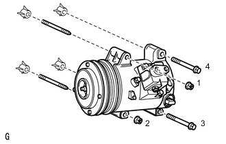
Using an E8 "TORX" socket wrench, install the with pulley compressor assembly with the 2 stud bolts.
- Torque:
- 10 N*m { 102 kgf*cm, 7 ft.*lbf }
-
Install the 2 bolts and 2 nuts.
- Torque:
- 25 N*m { 250 kgf*cm, 18 ft.*lbf }
Note
Tighten the nuts and bolts in the order shown in the illustration to install the with pulley compressor assembly.
-
Connect the connector.
-
-
CONNECT DISCHARGE HOSE SUB-ASSEMBLY
-
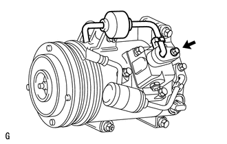
Remove the attached vinyl tape from the hose.
-
Sufficiently apply compressor oil to a new O-ring and the fitting surface of the with pulley compressor assembly.
Compressor oil ND-OIL 8 or equivalent -
Install the O-ring to the discharge hose sub-assembly.
-
Connect the discharge hose sub-assembly to the with pulley compressor assembly with the bolt.
- Torque:
- 9.8 N*m { 100 kgf*cm, 87 in.*lbf }
-
-
CONNECT SUCTION TUBE SUB-ASSEMBLY B
-
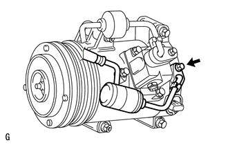
Remove the attached vinyl tape from the tube sub-assembly B.
-
Sufficiently apply compressor oil to a new O-ring and the fitting surface of the with pulley compressor assembly.
Compressor oil ND-OIL 8 or equivalent -
Install the O-ring to the cooler suction tube sub-assembly B.
-
Connect the suction tube sub-assembly B to the with pulley compressor assembly with the bolt.
- Torque:
- 9.8 N*m { 100 kgf*cm, 87 in.*lbf }
-
-
INSTALL EXHAUST MANIFOLD SUB-ASSEMBLY LH
for 1UR-FE: Click here
for 1UR-FSE: Click here
-
CONNECT CABLE TO NEGATIVE BATTERY TERMINAL
Note
When disconnecting the cable, some systems need to be initialized after the cable is reconnected Click here.
-
INSTALL COWL TOP VENTILATOR LOUVER
-
ADD COMPRESSOR OIL
-
CHARGE REFRIGERANT
-
WARM UP ENGINE
-
CHECK FOR LEAKAGE OF REFRIGERANT
-
INSPECT FOR EXHAUST GAS LEAK
-
PLACE FRONT WHEELS FACING STRAIGHT AHEAD
-
CHECK AND ADJUST FRONT WHEEL ALIGNMENT