CAN COMMUNICATION SYSTEM(for RHD), Diagnostic DTC:U1002
| DTC Code | DTC Name |
|---|---|
| U1002 | Lost Communication with Gateway Module (Main Body) |
DESCRIPTION
-
The main body ECU (driver side junction block) stores this DTC when no signals can be received from the ECUs that have been memorized as those connected to the MS bus circuit.
-
When the main body ECU (driver side junction block) receives a response signal from the ECUs connected to the MS bus circuit, the main body ECU (driver side junction block) recognizes and memorizes that the ECU is connected to the MS bus circuit. Based on this memorized data, the main body ECU (driver side junction block) monitors for malfunctions in the ECUs connected to the MS bus circuit when communicating with those ECUs. If the main body ECU (driver side junction block) cannot receive response signals from the ECUs that have been memorized as those connected to the MS bus circuit, the main body ECU (driver side junction block) determines that a malfunction exists.
-
If 2 or more DTCs are output during the DTC check, one side of the CAN branch wire may be open (one side of the CANH [CAN branch wire]/CANL [CAN branch wire] of the ECU and/or sensor is open).
| DTC Code | DTC Detection Condition | Trouble Area |
|---|---|---|
| U1002 | Lost communication with gateway module (MS bus) |
|
-
*1: w/ Tire Pressure Warning System
-
*2: w/ Pre-crash Safety System
WIRING DIAGRAM
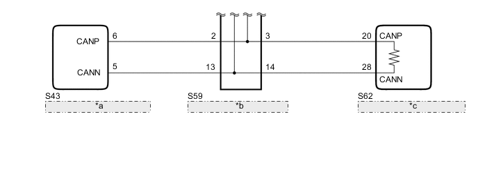
| *a | Power Trunk Lid Control ECU (Luggage Closer Motor Assembly) |
| *b | No. 12 Junction Connector |
| *c | Luggage Room Junction Block Assembly (Rear Junction Block ECU) |
CAUTION / NOTICE / HINT
Note
Before replacing the certification ECU (smart key ECU assembly), refer to the entry and start system Click here.
Tech Tips
Operating the engine switch, any switches or any doors triggers related ECU and sensor communication with the CAN, which causes resistance variation.
PROCEDURE
-
PRECAUTION
Note
After turning the engine switch off, waiting time may be required before disconnecting the cable from the battery terminal. Therefore, make sure to read the disconnecting the cable from the battery terminal notice before proceeding with work Click here.
NEXT 
-
DISCONNECT CABLE FROM NEGATIVE BATTERY TERMINAL
-
Disconnect the cable from the negative (-) battery terminal before measuring the resistances of the CAN main wire and the CAN branch wire.
CAUTION:
Wait at least 90 seconds after disconnecting the cable from the negative (-) battery terminal to disable the SRS system.
Note
When disconnecting the cable, some systems need to be initialized after the cable is reconnected Click here.
NEXT
-
-
CHECK CAN BUS WIRE (CAN MAIN WIRE FOR DISCONNECTION, BUS LINE FOR SHORT CIRCUIT)
-
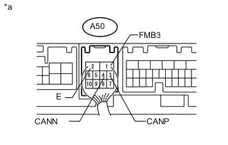
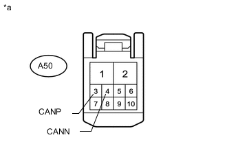
Text in Illustration *a Component with harness connected
(Front Multiplex Network Light ECU [Front Controller])
Measure the resistance according to the value(s) in the table below.
Standard Resistance Tester Connection Switch Condition Specified Condition Resistance: Malfunction A50-3 (CANP) - A50-4 (CANN) Engine switch off 54 to 69 Ω Below 53 Ω: Short in line A50-3 (CANP) - A50-4 (CANN) Engine switch off 54 to 69 Ω Higher than 70 Ω: Open in CAN main bus line A50-3 (CANP) - A50-1 (FMB3) Engine switch off 6 kΩ or higher Below 6 kΩ: +B short A50-4 (CANN) - A50-1 (FMB3) Engine switch off 6 kΩ or higher Below 6 kΩ: +B short A50-3 (CANP) - A50-2 (E) Engine switch off 200 Ω or higher Below 200 Ω: Ground short A50-4 (CANN) - A50-2 (E) Engine switch off 200 Ω or higher Below 200 Ω: Ground short Result Result Proceed to NG
-
Open in CAN main wire
A NG
-
Short in line
-
+B short
-
Ground short
B OK C -
B 
CHECK FOR SHORT IN CAN BUS WIRES (NO. 12 JUNCTION CONNECTOR SIDE) Click here
C
CHECK HARNESS AND CONNECTOR (MAIN BODY ECU - BATTERY AND BODY GROUND) Click here
A
-
-
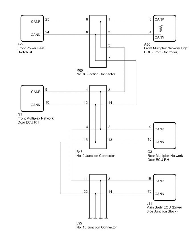
CHECK FOR OPEN IN CAN BUS MAIN WIRE (NO. 10 JUNCTION CONNECTOR - FRONT CONTROLLER)
-
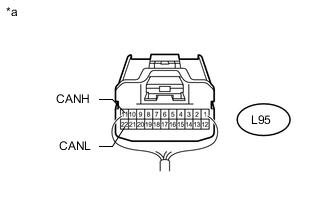
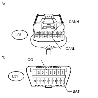
Text in Illustration *a Rear view of wire harness connector
(to No. 10 Junction Connector)
Disconnect the No. 10 junction connector.
-
Measure the resistance according to the value(s) in the table below.
Standard Resistance Tester Connection Switch Condition Specified Condition L95-11 (CANH) - L95-22 (CANL) Engine switch off 108 to 132 Ω
NG
CONNECT CONNECTOR Click here
OK
-
-
CHECK FOR OPEN IN CAN BUS MAIN WIRE (NO. 10 JUNCTION CONNECTOR - REAR JUNCTION BLOCK ECU)
-
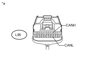
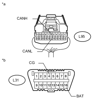
Text in Illustration *a Rear view of wire harness connector
(to No. 10 Junction Connector)
Measure the resistance according to the value(s) in the table below.
Standard Resistance Tester Connection Switch Condition Specified Condition L95-4 (CANH) - L95-15 (CANL) Engine switch off 108 to 132 Ω
OK 
REPLACE NO. 10 JUNCTION CONNECTOR
NG
CONNECT CONNECTOR Click here
-
-
CONNECT CONNECTOR
-
Reconnect the L95 No. 10 junction connector.
NEXT
-
-
CHECK FOR OPEN IN CAN BUS MAIN WIRE (NO. 9 JUNCTION CONNECTOR - FRONT CONTROLLER)
-
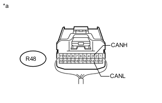
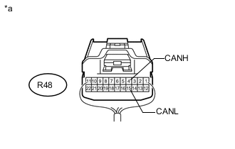
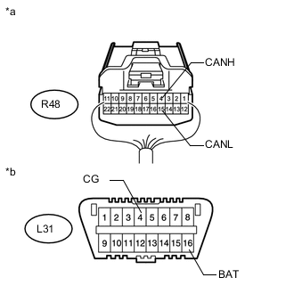
Text in Illustration *a Rear view of wire harness connector
(to No. 9 Junction Connector)
Disconnect the No. 9 junction connector.
-
Measure the resistance according to the value(s) in the table below.
Standard Resistance Tester Connection Switch Condition Specified Condition R48-3 (CANH) - R48-14 (CANL) Engine switch off 108 to 132 Ω
NG
CONNECT CONNECTOR Click here
OK
-
-
CHECK FOR OPEN IN CAN BUS MAIN WIRE (NO. 9 JUNCTION CONNECTOR - NO. 10 JUNCTION CONNECTOR)
-
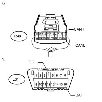
Text in Illustration *a Rear view of wire harness connector
(to No. 9 Junction Connector)
Measure the resistance according to the value(s) in the table below.
Standard Resistance Tester Connection Switch Condition Specified Condition R48-4 (CANH) - R48-15 (CANL) Engine switch off 108 to 132 Ω
OK
REPLACE NO. 9 JUNCTION CONNECTOR
NG
REPAIR OR REPLACE CAN MAIN WIRE OR CONNECTOR (NO. 9 JUNCTION CONNECTOR - NO. 10 JUNCTION CONNECTOR)
-
-
CONNECT CONNECTOR
-
Reconnect the R48 No. 9 junction connector.
NEXT
-
-
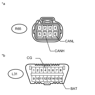
CHECK FOR OPEN IN CAN BUS MAIN WIRE (NO. 8 JUNCTION CONNECTOR - FRONT CONTROLLER)
-
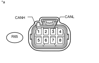
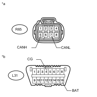
Text in Illustration *a Front view of wire harness connector
(to No. 8 Junction Connector)
Disconnect the No. 8 junction connector.
-
Measure the resistance according to the value(s) in the table below.
Standard Resistance Tester Connection Switch Condition Specified Condition R65-1 (CANH) - R65-3 (CANL) Engine switch off 108 to 132 Ω
NG
CONNECT CONNECTOR Click here
OK
-
-
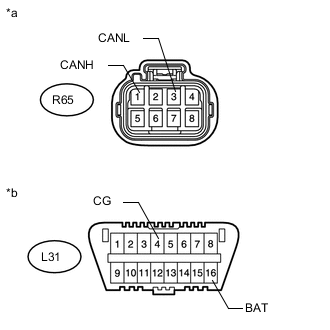
CHECK FOR OPEN IN CAN BUS MAIN WIRE (NO. 8 JUNCTION CONNECTOR - NO. 9 JUNCTION CONNECTOR)
-
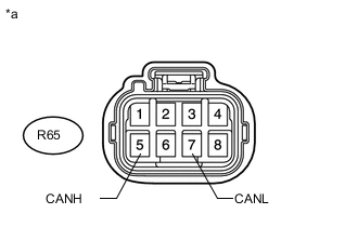
Text in Illustration *a Front view of wire harness connector
(to No. 8 Junction Connector)
Measure the resistance according to the value(s) in the table below.
Standard Resistance Tester Connection Switch Condition Specified Condition R65-5 (CANH) - R65-7 (CANL) Engine switch off 108 to 132 Ω
OK
REPLACE NO. 8 JUNCTION CONNECTOR
NG
REPAIR OR REPLACE CAN MAIN WIRE OR CONNECTOR (NO. 8 JUNCTION CONNECTOR - NO. 9 JUNCTION CONNECTOR)
-
-
CONNECT CONNECTOR
-
Reconnect the R65 No. 8 junction connector.
NEXT
-
-
CHECK FOR OPEN IN CAN BUS MAIN WIRE (FRONT CONTROLLER - NO. 8 JUNCTION CONNECTOR)
-
Text in Illustration *a Front view of wire harness connector
(to Front Multiplex Network Light ECU [Front Controller])
Disconnect the front multiplex network light ECU (front controller) connector.
-
Measure the resistance according to the value(s) in the table below.
Standard Resistance Tester Connection Switch Condition Specified Condition A50-3 (CANP) - A50-4 (CANN) Engine switch off 108 to 132 Ω
OK
REPLACE FRONT MULTIPLEX NETWORK LIGHT ECU (FRONT CONTROLLER)
NG
REPAIR OR REPLACE CAN MAIN WIRE CONNECTED TO FRONT CONTROLLER (FRONT CONTROLLER - NO. 8 JUNCTION CONNECTOR)
-
-
CONNECT CONNECTOR
-
Reconnect the L95 No. 10 junction connector.
NEXT
-
-
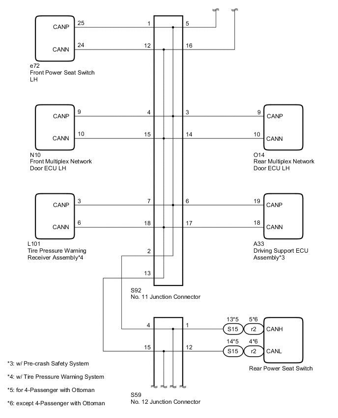
CHECK FOR OPEN IN CAN BUS MAIN WIRE (NO. 11 JUNCTION CONNECTOR - REAR JUNCTION BLOCK ECU)
-
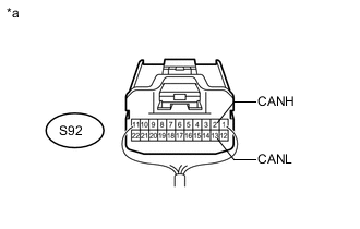
Text in Illustration *a Rear view of wire harness connector
(to No. 11 Junction Connector)
Disconnect the No. 11 junction connector.
-
Measure the resistance according to the value(s) in the table below.
Standard Resistance Tester Connection Switch Condition Specified Condition S92-2 (CANH) - S92-13 (CANL) Engine switch off 108 to 132 Ω
NG
CONNECT CONNECTOR Click here
OK
-
-
CHECK FOR OPEN IN CAN BUS MAIN WIRE (NO. 11 JUNCTION CONNECTOR - NO. 10 JUNCTION CONNECTOR)
-
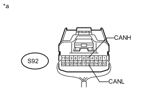
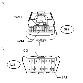
Text in Illustration *a Rear view of wire harness connector
(to No. 11 Junction Connector)
Measure the resistance according to the value(s) in the table below.
Standard Resistance Tester Connection Switch Condition Specified Condition S92-5 (CANH) - S92-16 (CANL) Engine switch off 108 to 132 Ω
OK
REPLACE NO. 11 JUNCTION CONNECTOR
NG
REPAIR OR REPLACE CAN MAIN WIRE OR CONNECTOR (NO. 11 JUNCTION CONNECTOR - NO. 10 JUNCTION CONNECTOR)
-
-
CONNECT CONNECTOR
-
Reconnect the S92 No. 11 junction connector.
NEXT
-
-
CHECK FOR OPEN IN CAN BUS MAIN WIRE (NO. 12 JUNCTION CONNECTOR - REAR JUNCTION BLOCK ECU)
-
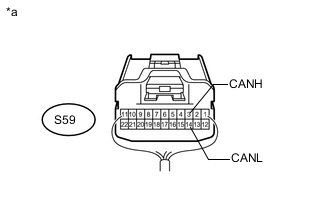
Text in Illustration *a Rear view of wire harness connector
(to No. 12 Junction Connector)
Disconnect the No. 12 junction connector.
-
Measure the resistance according to the value(s) in the table below.
Standard Resistance Tester Connection Switch Condition Specified Condition S59-3 (CANH) - S59-14 (CANL) Engine switch off 108 to 132 Ω
NG
CONNECT CONNECTOR Click here
OK
-
-
CHECK FOR OPEN IN CAN BUS MAIN WIRE (NO. 12 JUNCTION CONNECTOR - NO. 11 JUNCTION CONNECTOR)
-
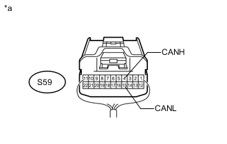
Text in Illustration *a Rear view of wire harness connector
(to No. 12 Junction Connector)
Measure the resistance according to the value(s) in the table below.
Standard Resistance Tester Connection Switch Condition Specified Condition S59-4 (CANH) - S59-15 (CANL) Engine switch off 108 to 132 Ω
OK
REPLACE NO. 12 JUNCTION CONNECTOR
NG
REPAIR OR REPLACE CAN MAIN WIRE OR CONNECTOR (NO. 12 JUNCTION CONNECTOR - NO. 11 JUNCTION CONNECTOR)
-
-
CONNECT CONNECTOR
-
Reconnect the S59 No. 12 junction connector.
NEXT
-
-
CHECK FOR OPEN IN CAN BUS MAIN WIRE (REAR JUNCTION BLOCK ECU - NO. 12 JUNCTION CONNECTOR)
-
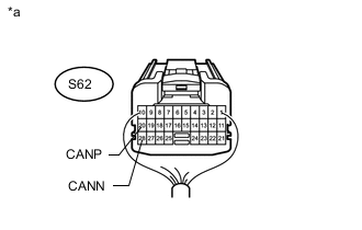
Text in Illustration *a Rear view of wire harness connector
(to Luggage Room Junction Block Assembly [Rear Junction Block ECU])
Disconnect the luggage room junction block assembly (rear junction block ECU) connector.
-
Measure the resistance according to the value(s) in the table below.
Standard Resistance Tester Connection Switch Condition Specified Condition S62-20 (CANP) - S62-28 (CANN) Engine switch off 108 to 132 Ω
OK
REPLACE LUGGAGE ROOM JUNCTION BLOCK ASSEMBLY
NG
REPAIR OR REPLACE CAN MAIN WIRE CONNECTED TO REAR JUNCTION BLOCK ECU (REAR JUNCTION BLOCK ECU - NO. 12 JUNCTION CONNECTOR)
-
-
CHECK FOR SHORT IN CAN BUS WIRES (NO. 12 JUNCTION CONNECTOR SIDE)
-
Text in Illustration *a Component with harness connected
(Front Multiplex Network Light ECU [Front Controller])
Disconnect the S59 No. 12 junction connector.
-
Measure the resistance according to the value(s) in the table below.
Standard Resistance Tester Connection Switch Condition Specified Condition A50-3 (CANP) - A50-4 (CANN) Engine switch off 108 to 132 Ω A50-3 (CANP) - A50-2 (E) Engine switch off 200 Ω or higher A50-4 (CANN) - A50-2 (E) Engine switch off 200 Ω or higher A50-3 (CANP) - A50-1 (FMB3) Engine switch off 6 kΩ or higher A50-4 (CANN) - A50-1 (FMB3) Engine switch off 6 kΩ or higher
NG
CONNECT CONNECTOR Click here
OK
-
-
CHECK FOR SHORT IN CAN BUS WIRES (NO. 12 JUNCTION CONNECTOR - REAR POWER SEAT SWITCH)
-
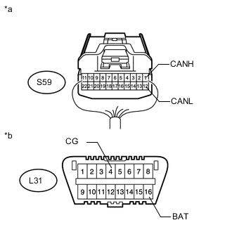
Text in Illustration *a Rear view of wire harness connector
(to No. 12 Junction Connector)
*b Front view of DLC3 Measure the resistance according to the value(s) in the table below.
Standard Resistance Tester Connection Switch Condition Specified Condition S59-1 (CANH) - S59-12 (CANL) Engine switch off 200 Ω or higher S59-1 (CANH) - L31-4 (CG) Engine switch off 200 Ω or higher S59-12 (CANL) - L31-4 (CG) Engine switch off 200 Ω or higher S59-1 (CANH) - L31-16 (BAT) Engine switch off 6 kΩ or higher S59-12 (CANL) - L31-16 (BAT) Engine switch off 6 kΩ or higher
NG
CONNECT CONNECTOR Click here
OK
-
-
CHECK FOR SHORT IN CAN BUS WIRES (NO. 12 JUNCTION CONNECTOR - POWER TRUNK LID CONTROL ECU)
-

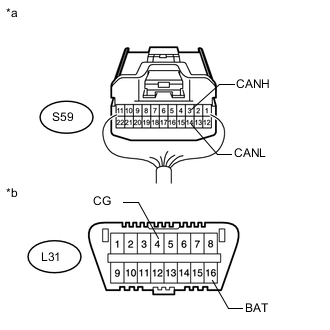
Text in Illustration *a Rear view of wire harness connector
(to No. 12 Junction Connector)
*b Front view of DLC3 Measure the resistance according to the value(s) in the table below.
Standard Resistance Tester Connection Switch Condition Specified Condition S59-2 (CANH) - S59-13 (CANL) Engine switch off 200 Ω or higher S59-2 (CANH) - L31-4 (CG) Engine switch off 200 Ω or higher S59-13 (CANL) - L31-4 (CG) Engine switch off 200 Ω or higher S59-2 (CANH) - L31-16 (BAT) Engine switch off 6 kΩ or higher S59-13 (CANL) - L31-16 (BAT) Engine switch off 6 kΩ or higher
NG
CONNECT CONNECTOR Click here
OK
-
-
CHECK FOR SHORT IN CAN BUS WIRES (NO. 12 JUNCTION CONNECTOR - REAR JUNCTION BLOCK ECU)
-
Text in Illustration *a Rear view of wire harness connector
(to No. 12 Junction Connector)
*b Front view of DLC3 Measure the resistance according to the value(s) in the table below.
Standard Resistance Tester Connection Switch Condition Specified Condition S59-3 (CANH) - S59-14 (CANL) Engine switch off 108 to 132 Ω S59-3 (CANH) - L31-4 (CG) Engine switch off 200 Ω or higher S59-14 (CANL) - L31-4 (CG) Engine switch off 200 Ω or higher S59-3 (CANH) - L31-16 (BAT) Engine switch off 6 kΩ or higher S59-14 (CANL) - L31-16 (BAT) Engine switch off 6 kΩ or higher
OK
REPLACE NO. 12 JUNCTION CONNECTOR
NG
CONNECT CONNECTOR Click here
-
-
CONNECT CONNECTOR
-
Reconnect the S59 No. 12 junction connector.
NEXT
-
-
CHECK FOR SHORT IN CAN BUS WIRES (REAR POWER SEAT SWITCH)
-
Disconnect the rear power seat switch connector.
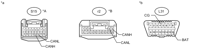
Text in Illustration *A for 4-Passenger with Ottoman *B except 4-Passenger with Ottoman *a Front view of wire harness connector
(to Rear Power Seat Switch)
*b Front view of DLC3 -
Measure the resistance according to the value(s) in the table below.
Standard Resistance for 4-Passenger with Ottoman Tester Connection Switch Condition Specified Condition S15-13 (CANH) - S15-14 (CANL) Engine switch off 54 to 69 Ω S15-13 (CANH) - L31-4 (CG) Engine switch off 200 Ω or higher S15-14 (CANL) - L31-4 (CG) Engine switch off 200 Ω or higher S15-13 (CANH) - L31-16 (BAT) Engine switch off 6 kΩ or higher S15-14 (CANL) - L31-16 (BAT) Engine switch off 6 kΩ or higher except 4-Passenger with Ottoman Tester Connection Switch Condition Specified Condition r2-5 (CANH) - r2-4 (CANL) Engine switch off 54 to 69 Ω r2-5 (CANH) - L31-4 (CG) Engine switch off 200 Ω or higher r2-4 (CANL) - L31-4 (CG) Engine switch off 200 Ω or higher r2-5 (CANH) - L31-16 (BAT) Engine switch off 6 kΩ or higher r2-4 (CANL) - L31-16 (BAT) Engine switch off 6 kΩ or higher Result Result Proceed to OK (for 4-Passenger with Ottoman) A OK (for 5-Passenger with Ottoman) B OK (for Power Seat) C OK (for Fixed Seat Type) D NG E
A
REPLACE REAR POWER SEAT SWITCH Click here
B
REPLACE REAR POWER SEAT SWITCH Click here
C
REPLACE REAR POWER SEAT SWITCH Click here
D
REPLACE REAR POWER SEAT SWITCH Click here
E
REPAIR OR REPLACE CAN BRANCH WIRE CONNECTED TO REAR POWER SEAT SWITCH (CANH, CANL)
-
-
CONNECT CONNECTOR
-
Reconnect the S59 No. 12 junction connector.
NEXT
-
-
CHECK FOR SHORT IN CAN BUS WIRES (POWER TRUNK LID CONTROL ECU)
-
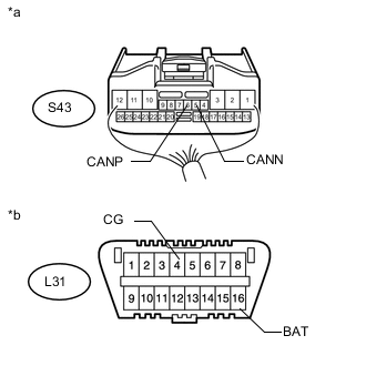
Text in Illustration *a Rear view of wire harness connector
(to Power Trunk Lid Control ECU [Luggage Closer Motor Assembly])
*b Front view of DLC3 Disconnect the power trunk lid control ECU (luggage closer motor assembly) connector.
-
Measure the resistance according to the value(s) in the table below.
Standard Resistance Tester Connection Switch Condition Specified Condition S43-6 (CANP) - S43-5 (CANN) Engine switch off 54 to 69 Ω S43-6 (CANP) - L31-4 (CG) Engine switch off 200 Ω or higher S43-5 (CANN) - L31-4 (CG) Engine switch off 200 Ω or higher S43-6 (CANP) - L31-16 (BAT) Engine switch off 6 kΩ or higher S43-5 (CANN) - L31-16 (BAT) Engine switch off 6 kΩ or higher
OK
REPLACE POWER TRUNK LID CONTROL ECU (LUGGAGE CLOSER MOTOR ASSEMBLY) Click here
NG
REPAIR OR REPLACE CAN BRANCH WIRE CONNECTED TO POWER TRUNK LID CONTROL ECU (CANP, CANN)
-
-
CONNECT CONNECTOR
-
Reconnect the S59 No. 12 junction connector.
NEXT
-
-
CHECK FOR SHORT IN CAN BUS WIRES (REAR JUNCTION BLOCK ECU)
-
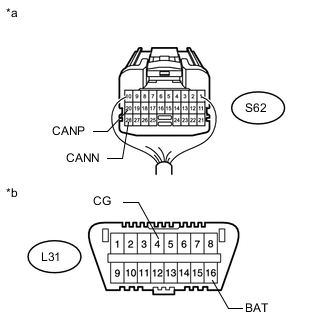
Text in Illustration *a Rear view of wire harness connector
(to Luggage Room Junction Block Assembly [Rear Junction Block ECU])
*b Front view of DLC3 Disconnect the luggage room junction block assembly (rear junction block ECU) connector.
-
Measure the resistance according to the value(s) in the table below.
Standard Resistance Tester Connection Switch Condition Specified Condition S62-20 (CANP) - S62-28 (CANN) Engine switch off 108 to 132 Ω S62-20 (CANP) - L31-4 (CG) Engine switch off 200 Ω or higher S62-28 (CANN) - L31-4 (CG) Engine switch off 200 Ω or higher S62-20 (CANP) - L31-16 (BAT) Engine switch off 6 kΩ or higher S62-28 (CANN) - L31-16 (BAT) Engine switch off 6 kΩ or higher
OK
REPLACE LUGGAGE ROOM JUNCTION BLOCK ASSEMBLY
NG
REPAIR OR REPLACE CAN MAIN WIRE CONNECTED TO REAR JUNCTION BLOCK ECU (CANP, CANN)
-
-
CONNECT CONNECTOR
-
Reconnect the S59 No. 12 junction connector.
NEXT
-
-
CHECK FOR OPEN IN CAN BUS MAIN WIRE (NO. 11 JUNCTION CONNECTOR - NO. 12 JUNCTION CONNECTOR)
-
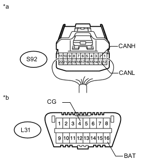
Text in Illustration *a Rear view of wire harness connector
(to No. 11 Junction Connector)
*b Front view of DLC3 Disconnect the No. 11 junction connector.
-
Measure the resistance according to the value(s) in the table below.
Standard Resistance Tester Connection Switch Condition Specified Condition S92-2 (CANH) - S92-13 (CANL) Engine switch off 108 to 132 Ω S92-2 (CANH) - L31-4 (CG) Engine switch off 200 Ω or higher S92-13 (CANL) - L31-4 (CG) Engine switch off 200 Ω or higher S92-2 (CANH) - L31-16 (BAT) Engine switch off 6 kΩ or higher S92-13 (CANL) - L31-16 (BAT) Engine switch off 6 kΩ or higher
NG
REPAIR OR REPLACE CAN MAIN WIRE OR CONNECTOR (NO. 11 JUNCTION CONNECTOR - NO. 12 JUNCTION CONNECTOR)
OK
-
-
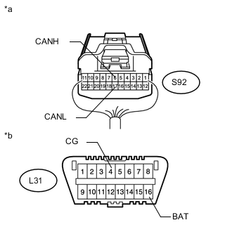
CHECK FOR SHORT IN CAN BUS WIRES (NO. 11 JUNCTION CONNECTOR SIDE)
-
Text in Illustration *a Component with harness connected
(Front Multiplex Network Light ECU [Front Controller])
Measure the resistance according to the value(s) in the table below.
Standard Resistance Tester Connection Switch Condition Specified Condition A50-3 (CANP) - A50-4 (CANN) Engine switch off 108 to 132 Ω A50-3 (CANP) - A50-2 (E) Engine switch off 200 Ω or higher A50-4 (CANN) - A50-2 (E) Engine switch off 200 Ω or higher A50-3 (CANP) - A50-1 (FMB3) Engine switch off 6 kΩ or higher A50-4 (CANN) - A50-1 (FMB3) Engine switch off 6 kΩ or higher
NG
CONNECT CONNECTOR Click here
OK
-
-
CHECK FOR SHORT IN CAN BUS WIRES (NO. 11 JUNCTION CONNECTOR - DRIVING SUPPORT ECU ASSEMBLY)
Note
For vehicles without a pre-crash safety system, go to "Check for Short in CAN Bus Wires (No. 11 Junction Connector - Tire Pressure Warning Receiver Assembly)".
-
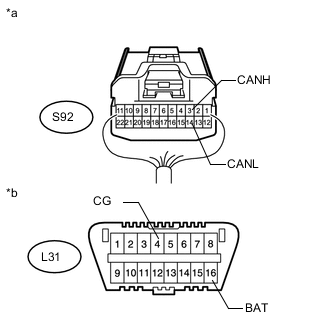
Text in Illustration *a Rear view of wire harness connector
(to No. 11 Junction Connector)
*b Front view of DLC3 Measure the resistance according to the value(s) in the table below.
Standard Resistance Tester Connection Switch Condition Specified Condition S92-6 (CANH) - S92-17 (CANL) Engine switch off 200 Ω or higher S92-6 (CANH) - L31-4 (CG) Engine switch off 200 Ω or higher S92-17 (CANL) - L31-4 (CG) Engine switch off 200 Ω or higher S92-6 (CANH) - L31-16 (BAT) Engine switch off 6 kΩ or higher S92-17 (CANL) - L31-16 (BAT) Engine switch off 6 kΩ or higher
NG
CONNECT CONNECTOR Click here
OK
-
-
CHECK SHORT IN CAN BUS WIRES (NO. 11 JUNCTION CONNECTOR - TIRE PRESSURE WARNING RECEIVER ASSEMBLY)
Note
For vehicles without a tire pressure warning system, go to "Check for Short in CAN Bus Wires (No. 11 Junction Connector - Rear Multiplex Network Door ECU LH)".
-
Text in Illustration *a Rear view of wire harness connector
(to No. 11 Junction Connector)
*b Front view of DLC3 Measure the resistance according to the value(s) in the table below.
Standard Resistance Tester Connection Switch Condition Specified Condition S92-7 (CANH) - S92-18 (CANL) Engine switch off 200 Ω or higher S92-7 (CANH) - L31-4 (CG) Engine switch off 200 Ω or higher S92-18 (CANL) - L31-4 (CG) Engine switch off 200 Ω or higher S92-7 (CANH) - L31-16 (BAT) Engine switch off 6 kΩ or higher S92-18 (CANL) - L31-16 (BAT) Engine switch off 6 kΩ or higher
NG
CONNECT CONNECTOR Click here
OK
-
-
CHECK FOR SHORT IN CAN BUS WIRES (NO. 11 JUNCTION CONNECTOR - REAR MULTIPLEX NETWORK DOOR ECU LH)
-
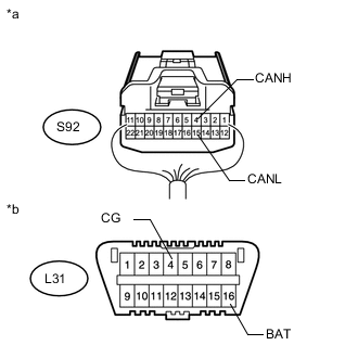
Text in Illustration *a Rear view of wire harness connector
(to No. 11 Junction Connector)
*b Front view of DLC3 Measure the resistance according to the value(s) in the table below.
Standard Resistance Tester Connection Switch Condition Specified Condition S92-3 (CANH) - S92-14 (CANL) Engine switch off 200 Ω or higher S92-3 (CANH) - L31-4 (CG) Engine switch off 200 Ω or higher S92-14 (CANL) - L31-4 (CG) Engine switch off 200 Ω or higher S92-3 (CANH) - L31-16 (BAT) Engine switch off 6 kΩ or higher S92-14 (CANL) - L31-16 (BAT) Engine switch off 6 kΩ or higher
NG
CONNECT CONNECTOR Click here
OK
-
-
CHECK FOR SHORT IN CAN BUS WIRES (NO. 11 JUNCTION CONNECTOR - FRONT MULTIPLEX NETWORK DOOR ECU LH)
-
Text in Illustration *a Rear view of wire harness connector
(to No. 11 Junction Connector)
*b Front view of DLC3 Measure the resistance according to the value(s) in the table below.
Standard Resistance Tester Connection Switch Condition Specified Condition S92-4 (CANH) - S92-15 (CANL) Engine switch off 200 Ω or higher S92-4 (CANH) - L31-4 (CG) Engine switch off 200 Ω or higher S92-15 (CANL) - L31-4 (CG) Engine switch off 200 Ω or higher S92-4 (CANH) - L31-16 (BAT) Engine switch off 6 kΩ or higher S92-15 (CANL) - L31-16 (BAT) Engine switch off 6 kΩ or higher
NG
CONNECT CONNECTOR Click here
OK
-
-
CHECK FOR SHORT IN CAN BUS WIRES (NO. 11 JUNCTION CONNECTOR - FRONT POWER SEAT SWITCH LH)
-
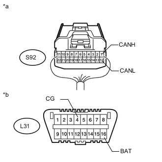
Text in Illustration *a Rear view of wire harness connector
(to No. 11 Junction Connector)
*b Front view of DLC3 Measure the resistance according to the value(s) in the table below.
Standard Resistance Tester Connection Switch Condition Specified Condition S92-1 (CANH) - S92-12 (CANL) Engine switch off 200 Ω or higher S92-1 (CANH) - L31-4 (CG) Engine switch off 200 Ω or higher S92-12 (CANL) - L31-4 (CG) Engine switch off 200 Ω or higher S92-1 (CANH) - L31-16 (BAT) Engine switch off 6 kΩ or higher S92-12 (CANL) - L31-16 (BAT) Engine switch off 6 kΩ or higher
OK
REPLACE NO. 11 JUNCTION CONNECTOR
NG
CONNECT CONNECTOR Click here
-
-
CONNECT CONNECTOR
-
Reconnect the S92 No. 11 junction connector.
NEXT
-
-
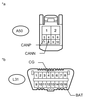
CHECK FOR SHORT IN CAN BUS WIRES (DRIVING SUPPORT ECU ASSEMBLY)
-
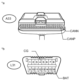
Text in Illustration *a Rear view of wire harness connector
(to Driving Support ECU Assembly)
*b Front view of DLC3 Disconnect the driving support ECU assembly connector.
-
Measure the resistance according to the value(s) in the table below.
Standard Resistance Tester Connection Switch Condition Specified Condition A33-19 (CANP) - A33-18 (CANN) Engine switch off 54 to 69 Ω A33-19 (CANP) - L31-4 (CG) Engine switch off 200 Ω or higher A33-18 (CANN) - L31-4 (CG) Engine switch off 200 Ω or higher A33-19 (CANP) - L31-16 (BAT) Engine switch off 6 kΩ or higher A33-18 (CANN) - L31-16 (BAT) Engine switch off 6 kΩ or higher
OK
REPLACE DRIVING SUPPORT ECU ASSEMBLY Click here
NG
REPAIR OR REPLACE CAN BRANCH WIRE CONNECTED TO DRIVING SUPPORT ECU ASSEMBLY (CANP, CANN)
-
-
CONNECT CONNECTOR
-
Reconnect the S92 No. 11 junction connector.
NEXT
-
-
CHECK FOR SHORT IN CAN BUS WIRES (TIRE PRESSURE WARNING RECEIVER ASSEMBLY)
-
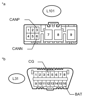
Text in Illustration *a Front view of wire harness connector
(to Tire Pressure Warning Receiver Assembly)
*b Front view of DLC3 Disconnect the tire pressure warning receiver assembly connector.
-
Measure the resistance according to the value(s) in the table below.
Standard Resistance Tester Connection Switch Condition Specified Condition L101-3 (CANP) - L101-6 (CANN) Engine switch off 54 to 69 Ω L101-3 (CANP) - L31-4 (CG) Engine switch off 200 Ω or higher L101-6 (CANN) - L31-4 (CG) Engine switch off 200 Ω or higher L101-3 (CANP) - L31-16 (BAT) Engine switch off 6 kΩ or higher L101-6 (CANN) - L31-16 (BAT) Engine switch off 6 kΩ or higher
OK
REPLACE TIRE PRESSURE WARNING RECEIVER ASSEMBLY Click here
NG
REPAIR OR REPLACE CAN BRANCH WIRE CONNECTED TO TIRE PRESSURE WARNING RECEIVER ASSEMBLY (CANP, CANN)
-
-
CONNECT CONNECTOR
-
Reconnect the S92 No. 11 junction connector.
NEXT
-
-
CHECK FOR SHORT IN CAN BUS WIRES (REAR MULTIPLEX NETWORK DOOR ECU LH)
-
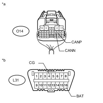
Text in Illustration *a Rear view of wire harness connector
(to Rear Multiplex Network Door ECU LH)
*b Front view of DLC3 Disconnect the rear multiplex network door ECU LH connector.
-
Measure the resistance according to the value(s) in the table below.
Standard Resistance Tester Connection Switch Condition Specified Condition O14-9 (CANP) - O14-10 (CANN) Engine switch off 54 to 69 Ω O14-9 (CANP) - L31-4 (CG) Engine switch off 200 Ω or higher O14-10 (CANN) - L31-4 (CG) Engine switch off 200 Ω or higher O14-9 (CANP) - L31-16 (BAT) Engine switch off 6 kΩ or higher O14-10 (CANN) - L31-16 (BAT) Engine switch off 6 kΩ or higher
OK
REPLACE REAR MULTIPLEX NETWORK DOOR ECU LH Click here
NG
REPAIR OR REPLACE CAN BRANCH WIRE CONNECTED TO REAR MULTIPLEX NETWORK DOOR ECU LH (CANP, CANN)
-
-
CONNECT CONNECTOR
-
Reconnect the S92 No. 11 junction connector.
NEXT
-
-
CHECK FOR SHORT IN CAN BUS WIRES (FRONT MULTIPLEX NETWORK DOOR ECU LH)
-

Text in Illustration *a Rear view of wire harness connector
(to Front Multiplex Network Door ECU LH)
*b Front view of DLC3 Disconnect the front multiplex network door ECU LH connector.
-
Measure the resistance according to the value(s) in the table below.
Standard Resistance Tester Connection Switch Condition Specified Condition N10-9 (CANP) - N10-10 (CANN) Engine switch off 54 to 69 Ω N10-9 (CANP) - L31-4 (CG) Engine switch off 200 Ω or higher N10-10 (CANN) - L31-4 (CG) Engine switch off 200 Ω or higher N10-9 (CANP) - L31-16 (BAT) Engine switch off 6 kΩ or higher N10-10 (CANN) - L31-16 (BAT) Engine switch off 6 kΩ or higher
OK
REPLACE FRONT MULTIPLEX NETWORK DOOR ECU LH Click here
NG
REPAIR OR REPLACE CAN BRANCH WIRE CONNECTED TO FRONT MULTIPLEX NETWORK DOOR ECU LH (CANP, CANN)
-
-
CONNECT CONNECTOR
-
Reconnect the S92 No. 11 junction connector.
NEXT
-
-
CHECK FOR OPEN IN CAN BUS MAIN WIRE (FRONT POWER SEAT SWITCH LH)
-

Text in Illustration *a Rear view of wire harness connector
(to Front Power Seat Switch LH)
*b Front view of DLC3 Disconnect the front power seat switch LH connector.
-
Measure the resistance according to the value(s) in the table below.
Standard Resistance Tester Connection Switch Condition Specified Condition e72-25 (CANP) - e72-24 (CANN) Engine switch off 54 to 69 Ω e72-25 (CANP) - L31-4 (CG) Engine switch off 200 Ω or higher e72-24 (CANN) - L31-4 (CG) Engine switch off 200 Ω or higher e72-25 (CANP) - L31-16 (BAT) Engine switch off 6 kΩ or higher e72-24 (CANN) - L31-16 (BAT) Engine switch off 6 kΩ or higher
OK
REPLACE FRONT POWER SEAT SWITCH LH Click here
NG
REPAIR OR REPLACE CAN BRANCH WIRE CONNECTED TO FRONT POWER SEAT SWITCH LH (CANP, CANN)
-
-
CONNECT CONNECTOR
-
Reconnect the S92 No. 11 junction connector.
NEXT
-
-
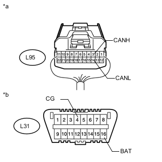
CHECK FOR SHORT IN CAN BUS WIRES (NO. 10 JUNCTION CONNECTOR - NO. 11 JUNCTION CONNECTOR)
-

Text in Illustration *a Rear view of wire harness connector
(to No. 10 Junction Connector)
*b Front view of DLC3 Disconnect the No. 10 junction connector.
-
Measure the resistance according to the value(s) in the table below.
Standard Resistance Tester Connection Switch Condition Specified Condition L95-4 (CANH) - L95-15 (CANL) Engine switch off 108 to 132 Ω L95-4 (CANH) - L31-4 (CG) Engine switch off 200 Ω or higher L95-15 (CANL) - L31-4 (CG) Engine switch off 200 Ω or higher L95-4 (CANH) - L31-16 (BAT) Engine switch off 6 kΩ or higher L95-15 (CANL) - L31-16 (BAT) Engine switch off 6 kΩ or higher
NG
REPAIR OR REPLACE CAN MAIN WIRE OR CONNECTOR (NO. 10 JUNCTION CONNECTOR - NO. 11 JUNCTION CONNECTOR)
OK
-
-
CHECK FOR SHORT IN CAN BUS WIRES (NO. 10 JUNCTION CONNECTOR SIDE)
-
Text in Illustration *a Component with harness connected
(Front Multiplex Network Light ECU [Front Controller])
Measure the resistance according to the value(s) in the table below.
Standard Resistance Tester Connection Switch Condition Specified Condition A50-3 (CANP) - A50-4 (CANN) Engine switch off 108 to 132 Ω A50-3 (CANP) - A50-2 (E) Engine switch off 200 Ω or higher A50-4 (CANN) - A50-2 (E) Engine switch off 200 Ω or higher A50-3 (CANP) - A50-1 (FMB3) Engine switch off 6 kΩ or higher A50-4 (CANN) - A50-1 (FMB3) Engine switch off 6 kΩ or higher
NG
CONNECT CONNECTOR Click here
OK
-
-
CHECK FOR SHORT IN CAN BUS WIRES (NO. 10 JUNCTION CONNECTOR - MAIN BODY ECU)
-
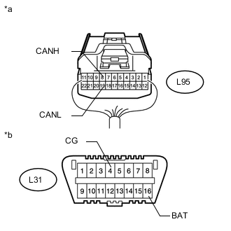
Text in Illustration *a Rear view of wire harness connector
(to No. 10 Junction Connector)
*b Front view of DLC3 Measure the resistance according to the value(s) in the table below.
Standard Resistance Tester Connection Switch Condition Specified Condition L95-3 (CANH) - L95-14 (CANL) Engine switch off 200 Ω or higher L95-3 (CANH) - L31-4 (CG) Engine switch off 200 Ω or higher L95-14 (CANL) - L31-4 (CG) Engine switch off 200 Ω or higher L95-3 (CANH) - L31-16 (BAT) Engine switch off 6 kΩ or higher L95-14 (CANL) - L31-16 (BAT) Engine switch off 6 kΩ or higher
NG
CONNECT CONNECTOR Click here
OK
-
-
CHECK FOR SHORT IN CAN BUS WIRES (NO. 10 JUNCTION CONNECTOR - CERTIFICATION ECU)
-
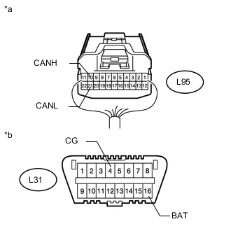
Text in Illustration *a Rear view of wire harness connector
(to No. 10 Junction Connector)
*b Front view of DLC3 Measure the resistance according to the value(s) in the table below.
Standard Resistance Tester Connection Switch Condition Specified Condition L95-5 (CANH) - L95-16 (CANL) Engine switch off 200 Ω or higher L95-5 (CANH) - L31-4 (CG) Engine switch off 200 Ω or higher L95-16 (CANL) - L31-4 (CG) Engine switch off 200 Ω or higher L95-5 (CANH) - L31-16 (BAT) Engine switch off 6 kΩ or higher L95-16 (CANL) - L31-16 (BAT) Engine switch off 6 kΩ or higher
NG
CONNECT CONNECTOR Click here
OK
-
-
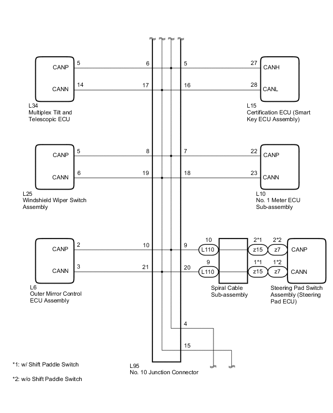
CHECK FOR SHORT IN CAN BUS WIRES (NO. 10 JUNCTION CONNECTOR - MULTIPLEX TILT AND TELESCOPIC ECU)
-
Text in Illustration *a Rear view of wire harness connector
(to No. 10 Junction Connector)
*b Front view of DLC3 Measure the resistance according to the value(s) in the table below.
Standard Resistance Tester Connection Switch Condition Specified Condition L95-6 (CANH) - L95-17 (CANL) Engine switch off 200 Ω or higher L95-6 (CANH) - L31-4 (CG) Engine switch off 200 Ω or higher L95-17 (CANL) - L31-4 (CG) Engine switch off 200 Ω or higher L95-6 (CANH) - L31-16 (BAT) Engine switch off 6 kΩ or higher L95-17 (CANL) - L31-16 (BAT) Engine switch off 6 kΩ or higher
NG
CONNECT CONNECTOR Click here
OK
-
-
CHECK FOR SHORT IN CAN BUS WIRES (NO. 10 JUNCTION CONNECTOR - NO. 1 METER ECU SUB-ASSEMBLY)
-

Text in Illustration *a Rear view of wire harness connector
(to No. 10 Junction Connector)
*b Front view of DLC3 Measure the resistance according to the value(s) in the table below.
Standard Resistance Tester Connection Switch Condition Specified Condition L95-7 (CANH) - L95-18 (CANL) Engine switch off 200 Ω or higher L95-7 (CANH) - L31-4 (CG) Engine switch off 200 Ω or higher L95-18 (CANL) - L31-4 (CG) Engine switch off 200 Ω or higher L95-7 (CANH) - L31-16 (BAT) Engine switch off 6 kΩ or higher L95-18 (CANL) - L31-16 (BAT) Engine switch off 6 kΩ or higher
NG
CONNECT CONNECTOR Click here
OK
-
-
CHECK FOR SHORT IN CAN BUS WIRES (NO. 10 JUNCTION CONNECTOR - WINDSHIELD WIPER SWITCH ASSEMBLY)
-
Text in Illustration *a Rear view of wire harness connector
(to No. 10 Junction Connector)
*b Front view of DLC3 Measure the resistance according to the value(s) in the table below.
Standard Resistance Tester Connection Switch Condition Specified Condition L95-8 (CANH) - L95-19 (CANL) Engine switch off 200 Ω or higher L95-8 (CANH) - L31-4 (CG) Engine switch off 200 Ω or higher L95-19 (CANL) - L31-4 (CG) Engine switch off 200 Ω or higher L95-8 (CANH) - L31-16 (BAT) Engine switch off 6 kΩ or higher L95-19 (CANL) - L31-16 (BAT) Engine switch off 6 kΩ or higher
NG
CONNECT CONNECTOR Click here
OK
-
-
CHECK FOR SHORT IN CAN BUS WIRES (NO. 10 JUNCTION CONNECTOR - STEERING PAD ECU)
-

Text in Illustration *a Rear view of wire harness connector
(to No. 10 Junction Connector)
*b Front view of DLC3 Measure the resistance according to the value(s) in the table below.
Standard Resistance Tester Connection Switch Condition Specified Condition L95-9 (CANH) - L95-20 (CANL) Engine switch off 200 Ω or higher L95-9 (CANH) - L31-4 (CG) Engine switch off 200 Ω or higher L95-20 (CANL) - L31-4 (CG) Engine switch off 200 Ω or higher L95-9 (CANH) - L31-16 (BAT) Engine switch off 6 kΩ or higher L95-20 (CANL) - L31-16 (BAT) Engine switch off 6 kΩ or higher
NG
CONNECT CONNECTOR Click here
OK
-
-
CHECK FOR SHORT IN CAN BUS WIRES (NO. 10 JUNCTION CONNECTOR - OUTER MIRROR SWITCH ASSEMBLY)
-
Text in Illustration *a Rear view of wire harness connector
(to No. 10 Junction Connector)
*b Front view of DLC3 Measure the resistance according to the value(s) in the table below.
Standard Resistance Tester Connection Switch Condition Specified Condition L95-10 (CANH) - L95-21 (CANL) Engine switch off 200 Ω or higher L95-10 (CANH) - L31-4 (CG) Engine switch off 200 Ω or higher L95-21 (CANL) - L31-4 (CG) Engine switch off 200 Ω or higher L95-10 (CANH) - L31-16 (BAT) Engine switch off 6 kΩ or higher L95-21 (CANL) - L31-16 (BAT) Engine switch off 6 kΩ or higher
OK
REPLACE NO. 10 JUNCTION CONNECTOR
NG
CONNECT CONNECTOR Click here
-
-
CONNECT CONNECTOR
-
Reconnect the L95 No. 10 junction connector.
NEXT
-
-
CHECK FOR SHORT IN CAN BUS WIRES (MAIN BODY ECU)
-
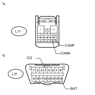
Text in Illustration *a Front view of wire harness connector
(to Main Body ECU [Driver Side Junction Block])
*b Front view of DLC3 Disconnect the main body ECU (driver side junction block) connector.
-
Measure the resistance according to the value(s) in the table below.
Standard Resistance Tester Connection Switch Condition Specified Condition L11-16 (CANP) - L11-15 (CANN) Engine switch off 54 to 69 Ω L11-16 (CANP) - L31-4 (CG) Engine switch off 200 Ω or higher L11-15 (CANN) - L31-4 (CG) Engine switch off 200 Ω or higher L11-16 (CANP) - L31-16 (BAT) Engine switch off 6 kΩ or higher L11-15 (CANN) - L31-16 (BAT) Engine switch off 6 kΩ or higher
OK
REPLACE MAIN BODY ECU (DRIVER SIDE JUNCTION BLOCK)
NG
REPAIR OR REPLACE CAN BRANCH WIRE CONNECTED TO MAIN BODY ECU (CANP, CANN)
-
-
CONNECT CONNECTOR
-
Reconnect the L95 No. 10 junction connector.
NEXT
-
-
CHECK FOR SHORT IN CAN BUS WIRES (CERTIFICATION ECU)
-
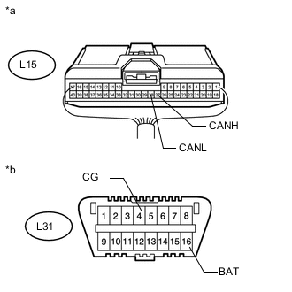
Text in Illustration *a Rear view of wire harness connector
(to Certification ECU [Smart Key ECU Assembly])
*b Front view of DLC3 Disconnect the certification ECU (smart key ECU assembly) connector.
-
Measure the resistance according to the value(s) in the table below.
Standard Resistance Tester Connection Switch Condition Specified Condition L15-27 (CANH) - L15-28 (CANL) Engine switch off 54 to 69 Ω L15-27 (CANH) - L31-4 (CG) Engine switch off 200 Ω or higher L15-28 (CANL) - L31-4 (CG) Engine switch off 200 Ω or higher L15-27 (CANH) - L31-16 (BAT) Engine switch off 6 kΩ or higher L15-28 (CANL) - L31-16 (BAT) Engine switch off 6 kΩ or higher
OK
REPLACE CERTIFICATION ECU (SMART KEY ECU ASSEMBLY)
NG
REPAIR OR REPLACE CAN BRANCH WIRE CONNECTED TO CERTIFICATION ECU (CANH, CANL)
-
-
CONNECT CONNECTOR
-
Reconnect the L95 No. 10 junction connector.
NEXT
-
-
CHECK FOR SHORT IN CAN BUS WIRES (MULTIPLEX TILT AND TELESCOPIC ECU)
-
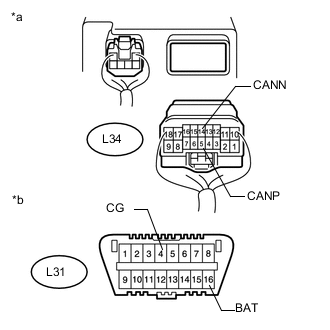
Text in Illustration *a Rear view of wire harness connector
(to Multiplex Tilt and Telescopic ECU)
*b Front view of DLC3 Disconnect the multiplex tilt and telescopic ECU connector.
-
Measure the resistance according to the value(s) in the table below.
Standard Resistance Tester Connection Switch Condition Specified Condition L34-5 (CANP) - L34-14 (CANN) Engine switch off 54 to 69 Ω L34-5 (CANP) - L31-4 (CG) Engine switch off 200 Ω or higher L34-14 (CANN) - L31-4 (CG) Engine switch off 200 Ω or higher L34-5 (CANP) - L31-16 (BAT) Engine switch off 6 kΩ or higher L34-14 (CANN) - L31-16 (BAT) Engine switch off 6 kΩ or higher
OK
REPLACE MULTIPLEX TILT AND TELESCOPIC ECU Click here
NG
REPAIR OR REPLACE CAN BRANCH WIRE CONNECTED TO MULTIPLEX TILT AND TELESCOPIC ECU (CANP, CANN)
-
-
CONNECT CONNECTOR
-
Reconnect the L95 No. 10 junction connector.
NEXT
-
-
CHECK FOR SHORT IN CAN BUS WIRES (NO. 1 METER ECU SUB-ASSEMBLY)
-
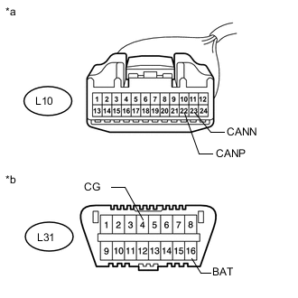
Text in Illustration *a Front view of wire harness connector
(to No. 1 Meter ECU Sub-assembly)
*b Front view of DLC3 Disconnect the No. 1 meter ECU sub-assembly connector.
-
Measure the resistance according to the value(s) in the table below.
Standard Resistance Tester Connection Switch Condition Specified Condition L10-22 (CANP) - L10-23 (CANN) Engine switch off 54 to 69 Ω L10-22 (CANP) - L31-4 (CG) Engine switch off 200 Ω or higher L10-23 (CANN) - L31-4 (CG) Engine switch off 200 Ω or higher L10-22 (CANP) - L31-16 (BAT) Engine switch off 6 kΩ or higher L10-23 (CANN) - L31-16 (BAT) Engine switch off 6 kΩ or higher
OK
REPLACE NO. 1 METER ECU SUB-ASSEMBLY Click here
NG
REPAIR OR REPLACE CAN BRANCH WIRE CONNECTED TO NO. 1 METER ECU SUB-ASSEMBLY (CANP, CANN)
-
-
CONNECT CONNECTOR
-
Reconnect the L95 No. 10 junction connector.
NEXT
-
-
CHECK FOR SHORT IN CAN BUS WIRES (WINDSHIELD WIPER SWITCH ASSEMBLY)
-
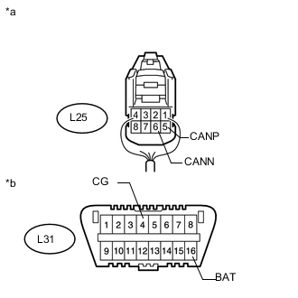
Text in Illustration *a Rear view of wire harness connector
(to Windshield Wiper Switch Assembly)
*b Front view of DLC3 Disconnect the windshield wiper switch assembly connector.
-
Measure the resistance according to the value(s) in the table below.
Standard Resistance Tester Connection Switch Condition Specified Condition L25-5 (CANP) - L25-6 (CANN) Engine switch off 54 to 69 Ω L25-5 (CANP) - L31-4 (CG) Engine switch off 200 Ω or higher L25-6 (CANN) - L31-4 (CG) Engine switch off 200 Ω or higher L25-5 (CANP) - L31-16 (BAT) Engine switch off 6 kΩ or higher L25-6 (CANN) - L31-16 (BAT) Engine switch off 6 kΩ or higher
OK
REPLACE WINDSHIELD WIPER SWITCH ASSEMBLY Click here
NG
REPAIR OR REPLACE CAN BRANCH WIRE CONNECTED TO WINDSHIELD WIPER SWITCH ASSEMBLY (CANP, CANN)
-
-
CONNECT CONNECTOR
-
Reconnect the L95 No. 10 junction connector.
NEXT
-
-
CHECK FOR SHORT IN CAN BUS WIRES (STEERING PAD ECU)
-
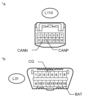
Text in Illustration *a Front view of wire harness connector
(to Spiral Cable Sub-assembly)
*b Front view of DLC3 Disconnect the spiral cable sub-assembly connector.
-
Measure the resistance according to the value(s) in the table below.
Standard Resistance Tester Connection Switch Condition Specified Condition L110-10 (CANP) - L110-9 (CANN) Engine switch off 54 to 69 Ω L110-10 (CANP) - L31-4 (CG) Engine switch off 200 Ω or higher L110-9 (CANN) - L31-4 (CG) Engine switch off 200 Ω or higher L110-10 (CANP) - L31-16 (BAT) Engine switch off 6 kΩ or higher L110-9 (CANN) - L31-16 (BAT) Engine switch off 6 kΩ or higher
NG
REPAIR OR REPLACE CAN BRANCH WIRE CONNECTED TO STEERING PAD ECU (CANP, CANN)
OK
-
-
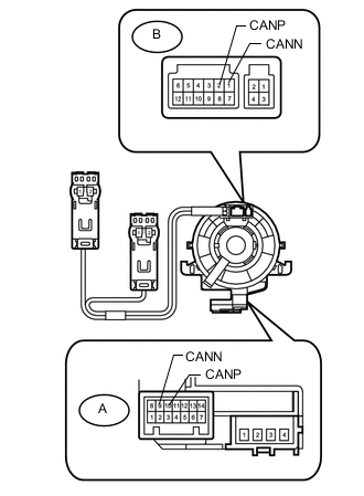
INSPECT SPIRAL CABLE SUB-ASSEMBLY
-
Remove the spiral cable sub-assembly Click here.
-
Set the spiral cable sub-assembly to the center position Click here.
-
Measure the resistance between each terminal of the spiral cable sub-assembly according to the table below.
-
After steering the spiral cable sub-assembly to the center position, rotate the spiral cable sub-assembly 2.5 times clockwise, and measure the resistance as shown. Then rotate the spiral cable sub-assembly 5 times counterclockwise, and measure the resistance as shown.
Standard Resistance Tester Connection Condition Specified Condition A-10 (CANP) - B-2 (CANP) Always Below 3 Ω A-9 (CANN) - B-1 (CANN) Always Below 3 Ω -
After steering the spiral cable sub-assembly to the center position, rotate the spiral cable sub-assembly 2.5 times clockwise, and measure the resistance as shown. Then while rotating the spiral cable sub-assembly 5 times counterclockwise, and measure the resistance as shown.
Standard Resistance Tester Connection Condition Specified Condition A-10 (CANP) - B-2 (CANP) Always Below 3 Ω A-9 (CANN) - B-1 (CANN) Always Below 3 Ω
OK
REPLACE STEERING PAD SWITCH ASSEMBLY (STEERING PAD ECU) Click here
NG
REPLACE SPIRAL CABLE SUB-ASSEMBLY Click here
-
-
CONNECT CONNECTOR
-
Reconnect the L95 No. 10 junction connector.
NEXT
-
-
CHECK FOR SHORT IN CAN BUS WIRES (OUTER MIRROR SWITCH ASSEMBLY)
-
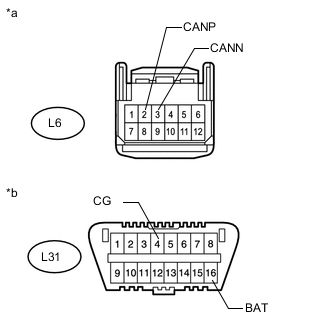
Text in Illustration *a Front view of wire harness connector
(to Outer Mirror Switch Assembly)
*b Front view of DLC3 Disconnect the outer mirror switch assembly connector.
-
Measure the resistance according to the value(s) in the table below.
Standard Resistance Tester Connection Switch Condition Specified Condition L6-2 (CANP) - L6-3 (CANN) Engine switch off 54 to 69 Ω L6-2 (CANP) - L31-4 (CG) Engine switch off 200 Ω or higher L6-3 (CANN) - L31-4 (CG) Engine switch off 200 Ω or higher L6-2 (CANP) - L31-16 (BAT) Engine switch off 6 kΩ or higher L6-3 (CANN) - L31-16 (BAT) Engine switch off 6 kΩ or higher
OK
REPLACE OUTER MIRROR SWITCH ASSEMBLY Click here
NG
REPAIR OR REPLACE CAN BRANCH WIRE CONNECTED TO OUTER MIRROR SWITCH ASSEMBLY (CANP, CANN)
-
-
CONNECT CONNECTOR
-
Reconnect the L95 No. 10 junction connector.
NEXT
-
-
CHECK FOR SHORT IN CAN BUS WIRES (NO. 9 JUNCTION CONNECTOR - NO. 10 JUNCTION CONNECTOR)
-
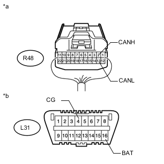
Text in Illustration *a Rear view of wire harness connector
(to No. 9 Junction Connector)
*b Front view of DLC3 Disconnect the No. 9 junction connector.
-
Measure the resistance according to the value(s) in the table below.
Standard Resistance Tester Connection Switch Condition Specified Condition R48-4 (CANH) - R48-15 (CANL) Engine switch off 108 to 132 Ω R48-4 (CANH) - L31-4 (CG) Engine switch off 200 Ω or higher R48-15 (CANL) - L31-4 (CG) Engine switch off 200 Ω or higher R48-4 (CANH) - L31-16 (BAT) Engine switch off 6 kΩ or higher R48-15 (CANL) - L31-16 (BAT) Engine switch off 6 kΩ or higher
NG
REPAIR OR REPLACE CAN MAIN WIRE OR CONNECTOR (NO. 9 JUNCTION CONNECTOR - NO. 10 JUNCTION CONNECTOR)
OK
-
-
CHECK FOR SHORT IN CAN BUS WIRES (NO. 9 JUNCTION CONNECTOR SIDE)
-
Text in Illustration *a Component with harness connected
(Front Multiplex Network Light ECU [Front Controller])
Measure the resistance according to the value(s) in the table below.
Standard Resistance Tester Connection Switch Condition Specified Condition A50-3 (CANP) - A50-4 (CANN) Engine switch off 108 to 132 Ω A50-3 (CANP) - A50-2 (E) Engine switch off 200 Ω or higher A50-4 (CANN) - A50-2 (E) Engine switch off 200 Ω or higher A50-3 (CANP) - A50-1 (FMB3) Engine switch off 6 kΩ or higher A50-4 (CANN) - A50-1 (FMB3) Engine switch off 6 kΩ or higher
NG
CONNECT CONNECTOR Click here
OK
-
-
CHECK FOR SHORT IN CAN BUS WIRES (NO. 9 JUNCTION CONNECTOR - FRONT MULTIPLEX NETWORK DOOR ECU RH)
-
Text in Illustration *a Rear view of wire harness connector
(to No. 9 Junction Connector)
*b Front view of DLC3 Measure the resistance according to the value(s) in the table below.
Standard Resistance Tester Connection Switch Condition Specified Condition R48-1 (CANH) - R48-12 (CANL) Engine switch off 200 Ω or higher R48-1 (CANH) - L31-4 (CG) Engine switch off 200 Ω or higher R48-12 (CANL) - L31-4 (CG) Engine switch off 200 Ω or higher R48-1 (CANH) - L31-16 (BAT) Engine switch off 6 kΩ or higher R48-12 (CANL) - L31-16 (BAT) Engine switch off 6 kΩ or higher
NG
CONNECT CONNECTOR Click here
OK
-
-
CHECK FOR SHORT IN CAN BUS WIRES (NO. 9 JUNCTION CONNECTOR - REAR MULTIPLEX NETWORK DOOR ECU RH)
-
Text in Illustration *a Rear view of wire harness connector
(to No. 9 Junction Connector)
*b Front view of DLC3 Measure the resistance according to the value(s) in the table below.
Standard Resistance Tester Connection Switch Condition Specified Condition R48-2 (CANH) - R48-13 (CANL) Engine switch off 200 Ω or higher R48-2 (CANH) - L31-4 (CG) Engine switch off 200 Ω or higher R48-13 (CANL) - L31-4 (CG) Engine switch off 200 Ω or higher R48-2 (CANH) - L31-16 (BAT) Engine switch off 6 kΩ or higher R48-13 (CANL) - L31-16 (BAT) Engine switch off 6 kΩ or higher
OK
REPLACE NO. 9 JUNCTION CONNECTOR
NG
CONNECT CONNECTOR Click here
-
-
CONNECT CONNECTOR
-
Reconnect the R48 No. 9 junction connector.
NEXT
-
-
CHECK FOR SHORT IN CAN BUS WIRES (FRONT MULTIPLEX NETWORK DOOR ECU RH)
-

Text in Illustration *a Rear view of wire harness connector
(to Front Multiplex Network Door ECU RH)
*b Front view of DLC3 Disconnect the front multiplex network door ECU RH connector.
-
Measure the resistance according to the value(s) in the table below.
Standard Resistance Tester Connection Switch Condition Specified Condition N1-9 (CANP) - N1-10 (CANN) Engine switch off 54 to 69 Ω N1-9 (CANP) - L31-4 (CG) Engine switch off 200 Ω or higher N1-10 (CANN) - L31-4 (CG) Engine switch off 200 Ω or higher N1-9 (CANP) - L31-16 (BAT) Engine switch off 6 kΩ or higher N1-10 (CANN) - L31-16 (BAT) Engine switch off 6 kΩ or higher
OK
REPLACE FRONT MULTIPLEX NETWORK DOOR ECU RH Click here
NG
REPAIR OR REPLACE CAN BRANCH WIRE CONNECTED TO FRONT MULTIPLEX NETWORK DOOR ECU RH (CANP, CANN)
-
-
CONNECT CONNECTOR
-
Reconnect the R48 No. 9 junction connector.
NEXT
-
-
CHECK FOR SHORT IN CAN BUS WIRES (REAR MULTIPLEX NETWORK DOOR ECU RH)
-

Text in Illustration *a Rear view of wire harness connector
(to Rear Multiplex Network Door ECU RH)
*b Front view of DLC3 Disconnect the rear multiplex network door ECU RH connector.
-
Measure the resistance according to the value(s) in the table below.
Standard Resistance Tester Connection Switch Condition Specified Condition O3-9 (CANP) - O3-10 (CANN) Engine switch off 54 to 69 Ω O3-9 (CANP) - L31-4 (CG) Engine switch off 200 Ω or higher O3-10 (CANN) - L31-4 (CG) Engine switch off 200 Ω or higher O3-9 (CANP) - L31-16 (BAT) Engine switch off 6 kΩ or higher O3-10 (CANN) - L31-16 (BAT) Engine switch off 6 kΩ or higher
OK
REPAIR REAR MULTIPLEX NETWORK DOOR ECU RH Click here
NG
REPAIR OR REPLACE CAN BRANCH WIRE CONNECTED TO REAR MULTIPLEX NETWORK DOOR ECU RH (CANP, CANN)
-
-
CONNECT CONNECTOR
-
Reconnect the R48 No. 9 junction connector.
NEXT
-
-
CHECK FOR SHORT IN CAN BUS WIRES (NO. 8 JUNCTION CONNECTOR - NO. 9 JUNCTION CONNECTOR)
-
Text in Illustration *a Front view of wire harness connector
(to No. 8 Junction Connector)
*b Front view of DLC3 Disconnect the No. 8 junction connector.
-
Measure the resistance according to the value(s) in the table below.
Standard Resistance Tester Connection Switch Condition Specified Condition R65-5 (CANH) - R65-7 (CANL) Engine switch off 108 to 132 Ω R65-5 (CANH) - L31-4 (CG) Engine switch off 200 Ω or higher R65-7 (CANL) - L31-4 (CG) Engine switch off 200 Ω or higher R65-5 (CANH) - L31-16 (BAT) Engine switch off 6 kΩ or higher R65-7 (CANL) - L31-16 (BAT) Engine switch off 6 kΩ or higher
NG
REPAIR OR REPLACE CAN MAIN WIRE OR CONNECTOR (NO. 8 JUNCTION CONNECTOR - NO. 9 JUNCTION CONNECTOR)
OK
-
-
CHECK FOR SHORT IN CAN BUS WIRES (NO. 8 JUNCTION CONNECTOR - FRONT POWER SEAT SWITCH RH)
-
Text in Illustration *a Front view of wire harness connector
(to No. 8 Junction Connector)
*b Front view of DLC3 Measure the resistance according to the value(s) in the table below.
Standard Resistance Tester Connection Switch Condition Specified Condition R65-6 (CANH) - R65-8 (CANL) Engine switch off 200 Ω or higher R65-6 (CANH) - L31-4 (CG) Engine switch off 200 Ω or higher R65-8 (CANL) - L31-4 (CG) Engine switch off 200 Ω or higher R65-6 (CANH) - L31-16 (BAT) Engine switch off 6 kΩ or higher R65-8 (CANL) - L31-16 (BAT) Engine switch off 6 kΩ or higher
NG
CONNECT CONNECTOR Click here
OK
-
-
CHECK FOR SHORT IN CAN BUS WIRES (NO. 8 JUNCTION CONNECTOR - FRONT CONTROLLER)
-
Text in Illustration *a Front view of wire harness connector
(to No. 8 Junction Connector)
*b Front view of DLC3 Measure the resistance according to the value(s) in the table below.
Standard Resistance Tester Connection Switch Condition Specified Condition R65-1 (CANH) - R65-3 (CANL) Engine switch off 108 to 132 Ω R65-1 (CANH) - L31-4 (CG) Engine switch off 200 Ω or higher R65-3 (CANL) - L31-4 (CG) Engine switch off 200 Ω or higher R65-1 (CANH) - L31-16 (BAT) Engine switch off 6 kΩ or higher R65-3 (CANL) - L31-16 (BAT) Engine switch off 6 kΩ or higher
OK
REPLACE NO. 8 JUNCTION CONNECTOR
NG
CONNECT CONNECTOR Click here
-
-
CONNECT CONNECTOR
-
Reconnect the R65 No. 8 junction connector.
NEXT
-
-
CHECK FOR SHORT IN CAN BUS WIRES (FRONT POWER SEAT SWITCH RH)
-
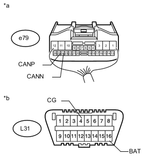
Text in Illustration *a Rear view of wire harness connector
(to Front Power Seat Switch RH)
*b Front view of DLC3 Disconnect the front power seat switch RH connector.
-
Measure the resistance according to the value(s) in the table below.
Standard Resistance Tester Connection Switch Condition Specified Condition e79-25 (CANP) - e79-24 (CANN) Engine switch off 54 to 69 Ω e79-25 (CANP) - L31-4 (CG) Engine switch off 200 Ω or higher e79-24 (CANN) - L31-4 (CG) Engine switch off 200 Ω or higher e79-25 (CANP) - L31-16 (BAT) Engine switch off 6 kΩ or higher e79-24 (CANN) - L31-16 (BAT) Engine switch off 6 kΩ or higher
OK
REPLACE FRONT POWER SEAT SWITCH RH Click here
NG
REPAIR OR REPLACE CAN BRANCH WIRE CONNECTED TO FRONT POWER SEAT SWITCH RH (CANP, CANN)
-
-
CONNECT CONNECTOR
-
Reconnect the R65 No. 8 junction connector.
NEXT
-
-
CHECK FOR SHORT IN CAN BUS WIRES (FRONT CONTROLLER)
-
Text in Illustration *a Front view of wire harness connector
(to Front Multiplex Network Light ECU [Front Controller])
*b Front view of DLC3 Disconnect the front multiplex network light ECU (front controller) connector.
-
Measure the resistance according to the value(s) in the table below.
Standard Resistance Tester Connection Switch Condition Specified Condition A50-3 (CANP) - A50-4 (CANN) Engine switch off 108 to 132 Ω A50-3 (CANP) - L31-4 (CG) Engine switch off 200 Ω or higher A50-4 (CANN) - L31-4 (CG) Engine switch off 200 Ω or higher A50-3 (CANP) - L31-16 (BAT) Engine switch off 6 kΩ or higher A50-4 (CANN) - L31-16 (BAT) Engine switch off 6 kΩ or higher
OK
REPLACE FRONT MULTIPLEX NETWORK LIGHT ECU (FRONT CONTROLLER)
NG
REPAIR OR REPLACE CAN MAIN WIRE CONNECTED TO FRONT CONTROLLER (CANP, CANN)
-
-
CHECK HARNESS AND CONNECTOR (MAIN BODY ECU - BATTERY AND BODY GROUND)
-
Connect the cable to the negative (-) battery terminal.
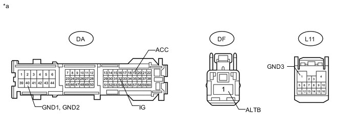
Text in Illustration *a Front view of wire harness connector
(to Main Body ECU [Driver Side Junction Block])
- - Note
When disconnecting the cable, some systems need to be initialized after the cable is reconnected Click here.
-
Disconnect the main body ECU (driver side junction block) connectors.
-
Measure the voltage according to the value(s) in the table below.
Standard Voltage Tester Connection Condition Specified Condition DF-1 (ALTB) - Body ground Always 11 to 14 V DA-19 (ACC) - Body ground Engine switch on (ACC) 11 to 14 V DA-32 (IG) - Body ground Engine switch on (IG) 11 to 14 V -
Measure the resistance according to the value(s) in the table below.
Standard Resistance Tester Connection Condition Specified Condition DA-40 (GND1) - Body ground Always Below 1 Ω DA-40 (GND2) - Body ground Always Below 1 Ω L11-1 (GND3) - DA-41 Always Below 1 Ω
OK
REPLACE MAIN BODY ECU (DRIVER SIDE JUNCTION BLOCK)
NG
REPAIR OR REPLACE HARNESS OR CONNECTOR
-