STEERING GEAR(for AWD with VGRS) INSTALLATION

CAUTION / NOTICE / HINT
Tech Tips
-
The procedures listed below are for the LHD.
-
Other than areas where instructions are provided, use the same procedures for the RHD and LHD.
PROCEDURE
-
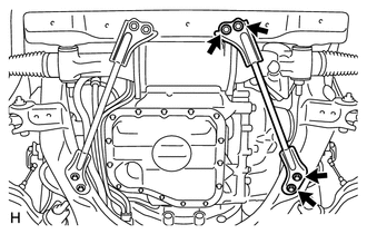
INSTALL POWER STEERING LINK ASSEMBLY
-
Install the power steering link to the front frame with the 2 bolts, 2 washers and 2 nuts.
- Torque:
- 150 N*m { 1530 kgf*cm, 111 ft.*lbf }
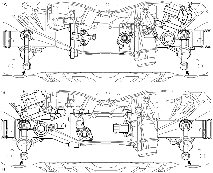
Text in Illustration *A for LHD *B for RHD -
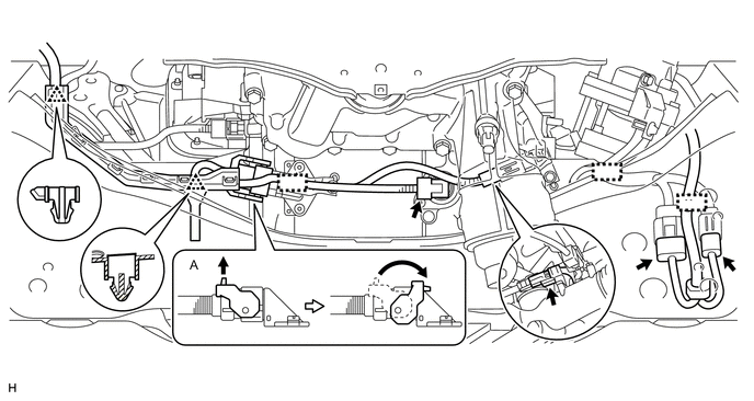
for LHD:
Connect the 5 connectors and attach the 2 clips, 3 clamps.
Tech Tips
Connect the connector A as shown in the illustration.
-
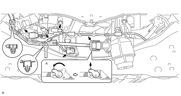
for RHD:
Connect the 5 connectors and attach the 2 clips, 3 clamps.
Tech Tips
Connect the connector A as shown in the illustration.
-
-
INSTALL FRONT NO. 1 STABILIZER BAR BUSH
-
INSTALL FRONT STABILIZER BAR
-
INSTALL FRONT NO. 1 STABILIZER BRACKET LH
-
INSTALL FRONT NO. 1 STABILIZER BRACKET RH
-
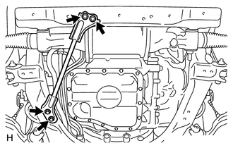
INSTALL NO. 2 FRONT STABILIZER BRACKET RH
-
Install the bracket and bolt.
- Torque:
- 22 N*m { 224 kgf*cm, 16 ft.*lbf }
-
Connect the 2 clamps.
-
-
CONNECT TIE ROD ASSEMBLY LH
-
CONNECT TIE ROD ASSEMBLY RH
Tech Tips
Use the same procedures described for the LH side.
-
CONNECT NO. 2 STEERING INTERMEDIATE SHAFT ASSEMBLY
-
INSTALL FRONT SUSPENSION MEMBER BRACKET SUB-ASSEMBLY RH
-
Install the front suspension member bracket with the 4 bolts.
- Torque:
- 59 N*m { 603 kgf*cm, 44 ft.*lbf }
-
-
INSTALL FRONT SUSPENSION MEMBER BRACKET SUB-ASSEMBLY LH
-
Install the front suspension member bracket with the 4 bolts.
- Torque:
- 59 N*m { 603 kgf*cm, 44 ft.*lbf }
-
-
INSTALL FRONT SUSPENSION MEMBER PROTECTOR LOWER
-
INSTALL NO. 2 ENGINE UNDER COVER
-
INSTALL NO. 1 ENGINE UNDER COVER
-
INSTALL FRONT WHEELS
- Torque:
- 140 N*m { 1428 kgf*cm, 103 ft.*lbf }
-
PLACE FRONT WHEELS FACING STRAIGHT AHEAD
-
CONNECT CABLE TO NEGATIVE BATTERY TERMINAL
Note
When disconnecting the cable, some systems need to be initialized after the cable is reconnected Click here.
-
CHECK SUSPENSION CONTROL SYSTEM
-
INSPECT AND ADJUST FRONT WHEEL ALIGNMENT
-
ADJUST HEADLIGHT AIMING
-
ADJUST OBJECT RECOGNITION CAMERA
-
CHECK SRS WARNING LIGHT
-
INITIALIZE ROTATION ANGLE SENSOR AND CALIBRATE TORQUE SENSOR ZERO POINT
-
PERFORM VARIABLE GEAR RATIO STEERING SYSTEM CALIBRATION