STEERING COLUMN ASSEMBLY(for AWD with VGRS) INSTALLATION
PROCEDURE
-
INSTALL STEERING COLUMN ASSEMBLY (TILT STEERING GEAR ASSEMBLY WITH MOTOR)
-
INSTALL NO. 2 STEERING INTERMEDIATE SHAFT ASSEMBLY
-
Install the clamp to the steering column hole cover sub-assembly.
-
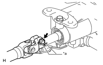
Text in Illustration *a Matchmark Align the matchmarks on the No. 2 steering intermediate shaft assembly and steering column.
-
Install the bolt.
- Torque:
- 35 N*m { 360 kgf*cm, 26 ft.*lbf }
-
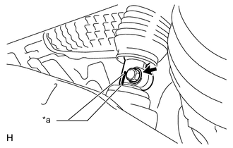
Text in Illustration *a Matchmark Align the matchmarks on the No. 2 steering intermediate shaft assembly and power steering link.
-
Install the bolt.
- Torque:
- 35 N*m { 360 kgf*cm, 26 ft.*lbf }
-
-
PLACE FRONT WHEELS FACING STRAIGHT AHEAD
-
INSTALL NO. 1 AIR DUCT SUB-ASSEMBLY
-
INSTALL NO. 1 LOWER INSTRUMENT PANEL AIRBAG ASSEMBLY
-
INSTALL TURN SIGNAL SWITCH ASSEMBLY WITH SPIRAL CABLE SUB-ASSEMBLY
-
INSTALL STEERING COLUMN COVER (w/o Driver Monitor Camera)
-
INSTALL STEERING COLUMN COVER (w/ Driver Monitor Camera)
-
ADJUST SPIRAL CABLE SUB-ASSEMBLY
-
INSTALL STEERING WHEEL ASSEMBLY
-
INSPECT STEERING WHEEL CENTER POINT
-
CONNECT CABLE TO NEGATIVE BATTERY TERMINAL
Note
Reset the AUTO TILT AWAY function setting to the previous condition by changing the customize parameter Click here.
-
INSTALL COWL TOP VENTILATOR LOUVER
-
CHECK SRS WARNING LIGHT
-
PERFORM INITIALIZATION
Note
When disconnecting the cable, some systems need to be initialized after the cable is reconnected Click here.