STEERING COLUMN ASSEMBLY(w/o VGRS) INSTALLATION
CAUTION / NOTICE / HINT
Tech Tips
-
Use the same procedures for the RHD and LHD.
-
The procedures listed below are for the LHD.
PROCEDURE
-
INSTALL STEERING COLUMN ASSEMBLY (TILT STEERING GEAR ASSEMBLY WITH MOTOR)
-
Install the steering column with the 4 nuts.
- Torque:
- 26 N*m { 260 kgf*cm, 19 ft.*lbf }
-
Connect the connectors and wire harness clamps to the steering column.
-
-
INSTALL NO. 2 STEERING INTERMEDIATE SHAFT ASSEMBLY
-
Install the clamp to the steering column hole shield.
-
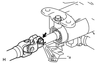
Text in Illustration *a Matchmark Align the matchmarks on the No. 2 steering intermediate shaft and steering column.
-
Install the bolt.
- Torque:
- 35 N*m { 360 kgf*cm, 26 ft.*lbf }
-
-
INSTALL STEERING INTERMEDIATE SHAFT
-
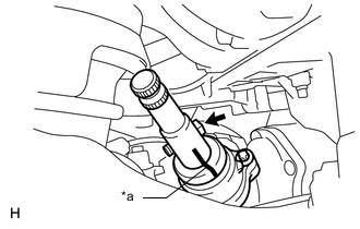
Text in Illustration *a Matchmark Align the matchmarks on the steering intermediate shaft and power steering link.
-
Install the bolt.
- Torque:
- 35 N*m { 360 kgf*cm, 26 ft.*lbf }
-
-
INSTALL STEERING SLIDING WITH SHAFT YOKE SUB-ASSEMBLY
-

Text in Illustration *a Matchmark Align the matchmarks on the No. 2 steering intermediate shaft and steering sliding with shaft yoke.
-
Align the matchmarks on the steering sliding with shaft yoke and steering intermediate shaft.
-
Temporarily install bolt B.
Note
Do not tighten the bolt.
-
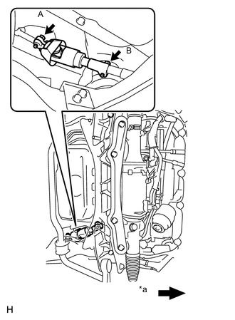
Text in Illustration *a Front of the vehicle Install bolt A and tighten bolt B.
- Torque:
- 35 N*m { 360 kgf*cm, 26 ft.*lbf }
-
-
PLACE FRONT WHEELS FACING STRAIGHT AHEAD
-
INSTALL NO. 1 AIR DUCT SUB-ASSEMBLY
-
Attach the 2 claws to install the air duct.
-
Install the bolt.
- Torque:
- 9.8 N*m { 100 kgf*cm, 87 in.*lbf }
-
Attach the 2 claws and install the wiring harness protector.
-
-
INSTALL NO. 1 LOWER INSTRUMENT PANEL AIRBAG ASSEMBLY
-
INSTALL TURN SIGNAL SWITCH ASSEMBLY WITH SPIRAL CABLE SUB-ASSEMBLY
-
Install the turn signal switch assembly with spiral cable to the steering column with the clamp.
-
Connect the connectors to the turn signal switch assembly with spiral cable.
-
-
INSTALL STEERING COLUMN COVER (w/ Driver Monitor Camera)
-
Connect the driver monitor connector.
-
Attach the claw and install the steering column cover upper.
-
Attach the 4 clips to install the steering column cover upper onto the instrument panel cluster finish panel.
-
Attach the 2 claws to install the steering column cover lower.
Note
Do not damage the tilt and telescopic switch.
-
Install the 3 screws.
-
-
INSTALL STEERING COLUMN COVER (w/o Driver Monitor Camera)
-
Attach the claw to install the steering column cover upper.
-
Attach the 4 clips to install the steering column cover upper onto the instrument panel cluster finish panel.
-
Attach the 2 claws to install the steering column cover lower.
Note
Do not damage the tilt and telescopic switch.
-
Install the 3 screws.
-
-
ADJUST SPIRAL CABLE SUB-ASSEMBLY
-
INSTALL STEERING WHEEL ASSEMBLY
-
INSPECT STEERING WHEEL CENTER POINT
-
CONNECT CABLE TO NEGATIVE BATTERY TERMINAL
Note
Reset the AUTO TILT AWAY function setting to the previous condition by changing the customize parameter Click here.
-
INSTALL COWL TOP VENTILATOR LOUVER
-
CHECK SRS WARNING LIGHT
-
PERFORM INITIALIZATION
Note
When disconnecting the cable, some systems need to be initialized after the cable is reconnected Click here.