ELECTRONICALLY CONTROLLED BRAKE SYSTEM, Diagnostic DTC:C1202/68

| DTC Code | DTC Name |
|---|---|
| C1202/68 | Master Reservoir Level Malfunction |
DESCRIPTION
When a fluid level drop in the brake master cylinder reservoir is detected, the signal is input to the skid control ECU.
| DTC Code | Information Code | DTC Detection Condition | Trouble Area |
|---|---|---|---|
| C1202/68 | 511 | The fluid level in the reservoir continues to drop when the pump motor is activated while braking. |
|
| ↑ | 512 | An open in the switch signal circuit continues for 2 seconds or more. |
|
WIRING DIAGRAM
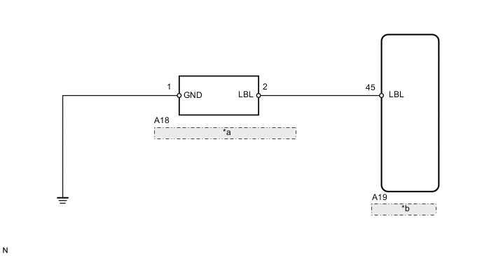
| *a | Brake Fluid Level Warning Switch |
| *b | Skid Control ECU |
CAUTION / NOTICE / HINT
Note
When replacing the skid control ECU, perform initialization of linear solenoid valve and calibration Click here.
PROCEDURE
-
CHECK BRAKE FLUID LEVEL IN RESERVOIR
-
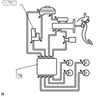
*1 Brake Booster Pump *2 Brake Actuator Check that the brake fluid level is sufficient.
OK Brake fluid level is proper. Tech Tips
-
If the fluid level drops, check for a fluid leak, and repair if found.
-
Check that the brake fluid leakage (Connection between accumulator and actuator, or actuator and wheel cylinder)
-
If no leak exists, add and adjust fluid and then check that the trouble code is not output again.
-
-
Check that there are no leaks from the connection between the accumulator pump and actuator.
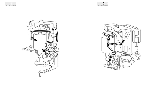
*1 for LHD: *2 for RHD: Tech Tips
As a visual check is very difficult, perform the check with the following procedures.
-
Bleed air from the brake actuator Click here.
-
Using the intelligent tester, check the data monitor of the accumulator pressure sensor.
Skid control ECU Tester Display Measurement Item/Range Normal Condition Diagnostic Note Accumulator Sensor Accumulator pressure sensor / min.: 0.00 V, max.: 5.00 V Specified value: 3.20 to 4.00 V - -
Wait for 30 seconds without operating the brake pedal. Then check the accumulator pressure sensor output value's change is within the specified range.
OK Accumulator pressure sensor output value's change is within 0.2 V. -
NG 
CHECK AND REPAIR BRAKE FLUID LEAKAGE AND ADD FLUID
OK 
-
-
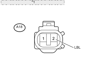
INSPECT BRAKE FLUID LEVEL WARNING SWITCH
-
*1 Component without harness connected: (Brake Fluid Level Warning Switch) Disconnect the A18 switch connector.
-
Measure the resistance according to the value(s) in the table below.
Tech Tips
A float is placed inside the reservoir. Its position can be changed by increasing/decreasing the level of brake fluid.
Standard resistance Tester Connection Switch Condition Specified Condition 1 (GND) - 2 (LBL) Float up (Switch OFF) 1.84 to 2.16 kΩ 1 (GND) - 2 (LBL) Float down (Switch ON) Below 1 Ω Tech Tips
If there is no problem after finishing the above check, adjust the brake fluid level to the MAX level.
NG
REPLACE BRAKE MASTER CYLINDER RESERVOIR ASSEMBLY
OK
-
-
CHECK HARNESS AND CONNECTOR (SKID CONTROL ECU - BRAKE FLUID LEVEL WARNING SWITCH)
-
Disconnect the A19 ECU connector.
-
Disconnect the A18 switch connector.
-
Measure the resistance according to the value(s) in the table below.
Standard resistance Tester Connection Condition Specified Condition A19-45 (LBL) - A18-2 (LBL) Always Below 1 Ω A19-45 (LBL) - Body ground Always 10 kΩ or higher A18-1 (GND) - Body ground Always Below 1 Ω
NG
REPAIR OR REPLACE HARNESS OR CONNECTOR
OK
-
-
CHECK SKID CONTROL ECU (SWITCH INPUT VOLTAGE)
-
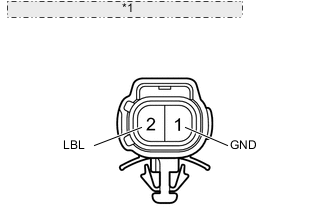
*1 Front view of wire harness connector: (to Brake Fluid Level Warning Switch) Reconnect the A19 ECU connector.
-
Disconnect the A18 switch connector.
-
Turn the engine switch on (IG).
-
Measure the voltage according to the value(s) in the table below.
Standard voltage Tester Connection Switch Condition Specified Condition A18-2 (LBL) - Body ground Engine switch on (IG) 8 to 14 V
NG
REPLACE SKID CONTROL ECU Click here
OK
-
-
RECONFIRM DTC
-
Clear the DTCs Click here.
-
Turn the engine switch on (IG).
-
Check if the same DTC is recorded Click here.
Tech Tips
Reinstall the sensors, connectors, etc. and restore the vehicle to its prior condition before rechecking for DTCs.
Result Result Proceed to DTC (C1202/68) is output A DTC (C1202/68) is not output B Tech Tips
If troubleshooting has been carried out according to the "PROBLEM SYMPTOMS TABLE", refer back to the table and proceed to the next step Click here.
A
REPLACE SKID CONTROL ECU Click here
B
END
-