BRAKE ACTUATOR(for LHD) REMOVAL

CAUTION / NOTICE / HINT
Note
While the battery is connected, even if the engine switch is off, the brake control system activates when the brake pedal is depressed or the door courtesy switch turns on. Therefore during servicing of the brake system components, do not operate the brake pedal and open/close the doors while the battery is connected.
PROCEDURE
-
REMOVE V-BANK COVER SUB-ASSEMBLY
-
REMOVE COWL TOP VENTILATOR LOUVER RH
-
REMOVE COWL TOP VENTILATOR LOUVER SUB-ASSEMBLY
-
DISCONNECT BRAKE ACCUMULATOR PUMP CONNECTOR
-
PERFORM ACCUMULATOR ZERO DOWN
-
PRECAUTION
Note
After turning the engine switch off, waiting time may be required before disconnecting the cable from the negative (-) battery terminal. Therefore, make sure to read the disconnecting the cable from the negative (-) battery terminal notice before proceeding with work Click here.
-
DISCONNECT CABLE FROM NEGATIVE BATTERY TERMINAL
Note
When disconnecting the cable, some systems need to be initialized after the cable is reconnected Click here.
-
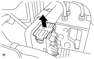
REMOVE SKID CONTROL ECU
-
REMOVE SKID CONTROL ECU BRACKET
-
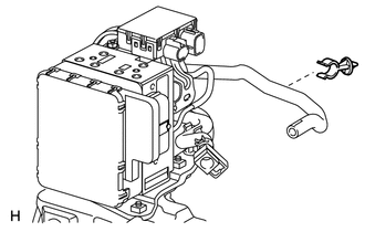
DISCONNECT NO. 3 RELAY BLOCK
-
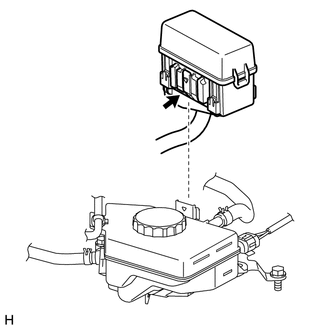
While pushing the claw of the No. 3 relay block, pull out the No. 3 relay block and disconnect it from the reservoir bracket.
Note
Do not allow brake fluid to contact the No. 3 relay block.
-
-
REMOVE BRAKE MASTER CYLINDER RESERVOIR ASSEMBLY
-
REMOVE NO. 1 RESERVOIR HOSE
-
REMOVE RESERVOIR BRACKET
-
REMOVE FRONT WHEEL
-
DISCONNECT BRAKE TUBE
-
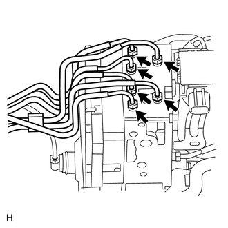
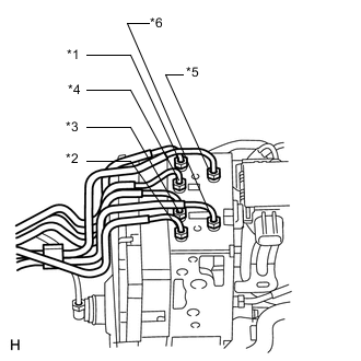
Using a union nut wrench, disconnect the 6 brake tubes from the actuator.
-
Use tags or make a note to identify the reconnection locations.
-
*1: To FR RH
-
*2: To FR LH
-
*3: To: RR RH
-
*4: To RR LH
-
*5: From Master Cylinder
-
*6: From Stroke Simulator
-
-
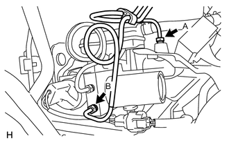
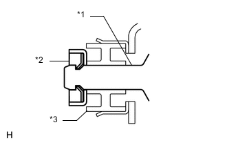
Using a union nut wrench, disconnect the No. 1 (labeled A) and No. 2 (labeled B) brake actuator tubes.
Note
Do not damage the No. 1 and No. 2 brake actuator tubes.
-
-
REMOVE BRAKE ACTUATOR AND BRAKE ACCUMULATOR PUMP ASSEMBLY
-
Release the lock lever and disconnect the brake actuator connector.
Note
Do not allow brake fluid to contact the connector face.
-
Disconnect the No. 1 brake actuator hose from the clamp and then remove the clamp.
-
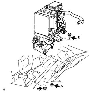
Disconnect the front fender liner rear side and then remove the 2 nuts (labeled A).
-
Remove the bolt (labeled B) and brake actuator and brake accumulator pump.
Note
-
Do not damage the brake tubes.
-
When removing the brake actuator and brake accumulator pump from the vehicle, do not hold the connector, harness, hose or tube parts.
-
Do not drop the brake actuator and brake accumulator pump. Do not use parts that have been dropped.
-
-
-
REMOVE NO. 5 BRAKE ACTUATOR BRACKET
-
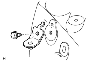
Remove the bolt and No. 5 brake actuator bracket.
-
-
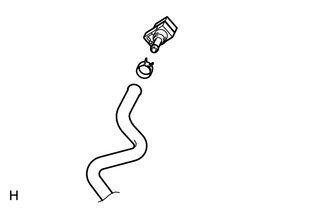
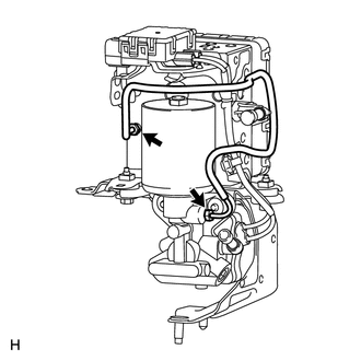
REMOVE NO. 1 BRAKE ACTUATOR HOSE
Note
When disconnecting the hose, be careful that there is no excessive weight applied to the union of the brake actuator (especially in the union rotation direction).
-
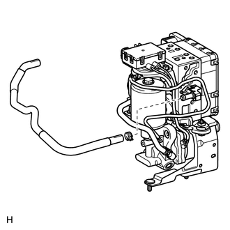
Remove the hose clip and the No. 1 brake actuator hose.
-
-
REMOVE BRAKE ACTUATOR PROTECTOR
-
Remove the protector.
-
-
REMOVE NO. 2 BRAKE ACTUATOR HOSE
Note
When disconnecting the hose, be careful that there is no excessive weight applied to the union of the brake accumulator pump (especially in the union rotation direction).
-
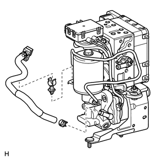
Disconnect the No. 2 brake actuator hose from the No. 3 brake actuator bracket and then remove the clamp.
-
Remove the hose clip and No. 2 brake actuator hose.
-
Remove the hose clip and reservoir connector.
-
-
REMOVE NO. 3 BRAKE ACTUATOR TUBE
Note
-
Do not damage the No. 3 brake actuator tube, brake actuator and brake accumulator pump.
-
When removing the No. 3 brake actuator tube, hold the tube, brake actuator and brake accumulator pump securely.
-
Using a union nut wrench, disconnect the No. 3 brake actuator tube.
-
-
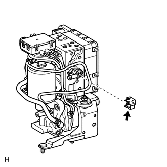
DISCONNECT BRAKE ACCUMULATOR PUMP CONNECTOR BOX
-
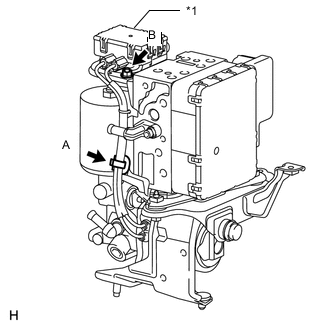
Text in Illustration *1 Connector Box Disconnect the brake accumulator pump connector box as follows:
-
Detach the wiring harness clamp (labeled A).
-
Remove the nut (labeled B) and connector box.
-
-
-
REMOVE NO. 4 BRAKE ACTUATOR BRACKET
-
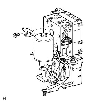
Remove the bolt and No. 4 brake actuator bracket.
-
-
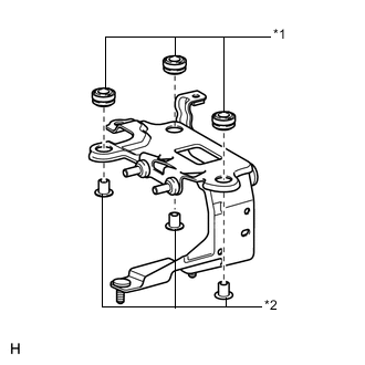
REMOVE BRAKE ACCUMULATOR PUMP
-
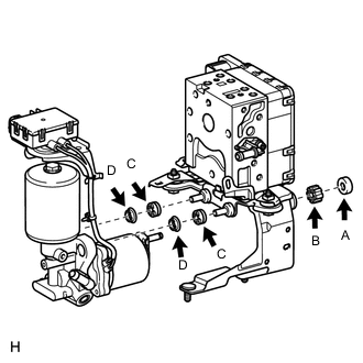
Break and remove the brake actuator bracket clamp (labeled A), and then remove the brake accumulator pump.
Text in Illustration *1 Brake Accumulator Pump *2 Clamp (A) *3 Bush (B) -
Remove the brake booster pump bush (labeled B) from the brake actuator bracket.
-
Remove the brake booster pump bushes (labeled C) and brake booster pump collars (labeled D) from the brake accumulator pump.
-
-
REMOVE BRAKE ACTUATOR
-
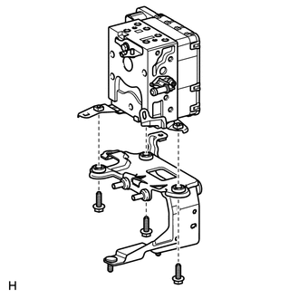
Remove the 3 bolts, brake actuator bracket and brake actuator.
-
Text in Illustration *1 Cushion *2 Spacer Remove the 3 cushions and 3 spacers from the brake actuator bracket.
-
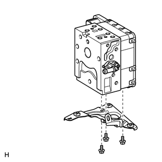
Remove the 3 bolts and No. 3 brake actuator bracket from the brake actuator.
-