FRONT WHEEL ALIGNMENT(for 2WD) ADJUSTMENT
PROCEDURE
-
INSPECT TIRES
-
MEASURE VEHICLE HEIGHT (w/ Air Suspension)
-
Bounce the vehicle at the corners up and down to stabilize the suspension and inspect the vehicle height.
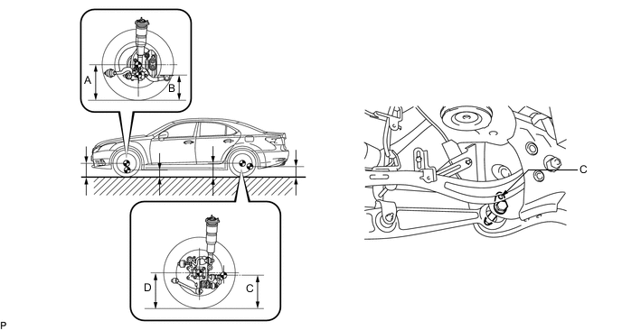
Measuring points A Ground clearance of front wheel center B Ground clearance of front center position of front suspension lower No. 2 arm assembly front bush installation C Ground clearance of pit center of the attachment rear suspension arm D Ground clearance of rear wheel center Standard Vehicle Height (Unloaded Vehicle) Vehicle Specification Front (A - B) Rear (D - C) for Sport Package 108 mm (4.25 in.) 103 mm (4.06 in.) except Sport Package 98 mm (3.86 in.) 93 mm (3.66 in.) Note
-
The standard value shown here is a value that is used for adjusting the wheel alignment and does not indicate the height of an actual vehicle.
-
Before inspecting the wheel alignment, adjust the vehicle height to the specified value.
Tech Tips
Bounce the vehicle up and down at the corners to stabilize the suspension and inspect the vehicle height.
-
-
-
MEASURE VEHICLE HEIGHT (w/o Air Suspension)
-
Bounce the vehicle at the corners up and down to stabilize the suspension and inspect the vehicle height.
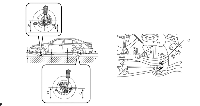
Measuring points A Ground clearance of front wheel center B Ground clearance of front center position of front suspension lower No. 2 arm assembly front bush installation C Ground clearance of pit center of the attachment rear suspension arm D Ground clearance of rear wheel center Standard Vehicle Height (Unloaded Vehicle) Front (A - B) Rear (D - C) 91 mm (3.58 in.) 76 mm (2.99 in.) Note
-
The standard value shown here is a value that is used for adjusting the wheel alignment and does not indicate the height of an actual vehicle.
-
Before inspecting the wheel alignment, adjust the vehicle height to the specified value.
Tech Tips
Bounce the vehicle up and down at the corners to stabilize the suspension and inspect the vehicle height.
-
-
-
INSPECT TOE-IN
-
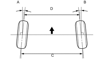
Bounce the vehicle up and down at the corners to stabilize the suspension and inspect toe-in.
Standard Toe-in (Unloaded Vehicle) Toe-in (total) A + B C - D 0°00' +/-10'
(0.00°+/-0.16°)
0.0 +/-2.0 mm
(0.00 +/-0.08 in.)
Tech Tips
If toe-in is not within the specified range, adjust it at the rack ends.
-
-
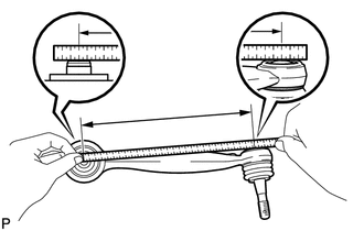
ADJUST TOE-IN
-
Measure the thread lengths of the right and left rack ends.
Standard Difference in thread length of 1.5 mm (0.059 in.) or less -
Remove the rack boot set clips.
-
Loosen the tie rod end lock nuts.
-
Adjust the rack ends if the difference in thread length between the right and left rack ends is not within the specified range.
-
Extend the shorter rack end if the measured toe-in deviates toward the outer-side.
-
Shorten the longer rack end if the measured toe-in deviates toward the inner-side.
-
-
Turn the right and left rack ends by an equal amount to adjust toe-in.
Tech Tips
Try to adjust toe-in to the center of the specified range.
-
Make sure that the lengths of the right and left rack ends are the same.
-
Torque the tie rod end lock nuts.
- Torque:
- 56 N*m { 570 kgf*cm, 41 ft.*lbf }
Note
Temporarily tighten the lock nut while holding the hexagonal part of the steering rack end so that the lock nut and the steering rack end do not turn together. Hold the width across flat of the tie rod end and tighten the lock nut.
-
Perform the VGRS system calibration.
-
Place the boots on the seats and install the clips.
Tech Tips
-
Make sure that the boots are not twisted.
-
Make sure that the clips are facing towards the front of the vehicle.
-
-
-
INSPECT WHEEL ANGLE
-
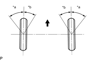
*a Inside *b Outside 
Front of Vehicle Turn the steering wheel fully to the left and right and measure the turning angle.
Standard wheel turning angle (Unloaded Vehicle) Vehicle Specification Inside wheel Outside wheel: Reference w/ Air Suspension
235/50R18
41°10' +/-2°00' (41.17°+/-2.00°) 35°4' (35.07°) w/o Air Suspension
235/50R18 (RHD)
41°20' +/-2°00' (41.33°+/-2.00°) 35°12' (35.20°) w/o Air Suspension
235/50R18 (LHD)
40°23' +/-2°00' (40.38°+/-2.00°) 34°35' (34.58°) w/ Air Suspension
245/45R19
40°13' +/-2°00' (40.22°+/-2.00°) 34°26' (34.43°) w/o Air Suspension
245/45R19
40°23' +/-2°00' (40.38°+/-2.00°) 34°35' (34.58°) for Sport Package 39°57' +/-2°00' (39.95°+/-2.00°) 34°14' (34.23°) If the right and left inside wheel angles differ from the specified range, check the right and left rack end lengths.
-
-
INSPECT CAMBER, CASTER AND STEERING AXIS INCLINATION
-
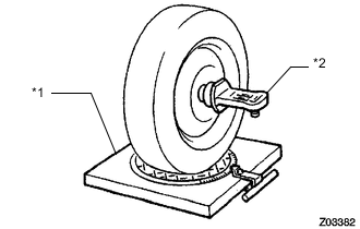
*1 Alignment Tester *2 Camber-caster-steering axis inclination Gauge Put the front wheels on the center of the alignment tester.
-
Remove the center ornament.
-
Install the camber-caster-steering axis inclination gauge at the center of the axle hub or drive shaft.
-
Inspect the camber, caster and steering axis inclination.
Standard Camber Inclination (Unloaded Vehicle) Vehicle Specification Camber Inclination Left - right error w/ Air Suspension -0°25' +/-45' (-0.42° +/-0.75°) 30' (0.50°) or less w/o Air Suspension -0°16' +/-45' (-0.27° +/-0.75°) 30' (0.50°) or less for Sport Package -0°39' +/-45' (-0.65° +/-0.75°) 30' (0.50°) or less Standard Caster Inclination (Unloaded Vehicle) Vehicle Specification Caster Inclination Left - right error w/ Air Suspension 6°57' +/-45' (6.95° +/-0.75°) 45' (0.75°) or less w/o Air Suspension 6°28' +/-45' (6.47° +/-0.75°) 45' (0.75°) or less for Sport Package 7°21' +/-45' (7.35° +/-0.75°) 45' (0.75°) or less Standard Steering Axis Inclination (Unloaded Vehicle) Vehicle Specification Steering Axis Inclination Left - right error w/ Air Suspension 9°26' +/-45' (9.43° +/-0.75°) 30' (0.50°) or less w/o Air Suspension 9°14' +/-45' (9.23° +/-0.75°) 30' (0.50°) or less for Sport Package 9°44' +/-45' (9.73° +/-0.75°) 30' (0.50°) or less Note
-
Inspect while the vehicle is empty.
-
The maximum tolerance of right and left difference for the camber is 30' or less.
-
The maximum tolerance of right and left difference for the caster is 45' or less.
-
-
Remove the camber-caster-steering axis inclination gauge and attachment.
-
Install the center ornament.
If the caster and steering axis inclination are not within the specified values, after the camber has been correctly adjusted, recheck the suspension parts for damaged and/or worn out parts.
-
-
ADJUST CAMBER AND CASTER
-
Lift up the vehicle so that there is no load on the tires.
-
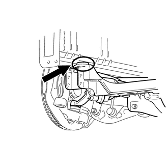
Place a mark (with spray, etc.) over the front right vehicle side attachment area of the crossmember, which is indicated in the illustration.
-
Place a mark (with spray, etc.) over the front left vehicle side attachment area of the crossmember.
-
Loosen areas as necessary so that the front suspension crossmember can move.
-
Move the front suspension crossmember and adjust the camber and caster.
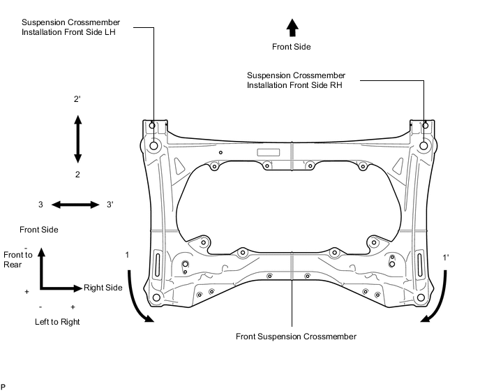
Relative alignment change based on amount of suspension crossmember movement in each direction Alignment Change Amount Relative Amount of Movement Between Suspension Crossmember and Vehicle Body 1 Suspension Crossmember Turn Caster Camber Suspension Crossmember Installation Front Side LH Suspension Crossmember Installation Front Side RH LH RH LH RH Front to Rear Left to Right Front to Rear Left to Right - 10' + 3' + 3' - 3' + 1 mm
(+ 0.0394 in.)
- - - 1' Caster Camber Suspension Crossmember Installation Front Side LH Suspension Crossmember Installation Front Side RH LH RH LH RH Front to Rear Left to Right Front to Rear Left to Right + 3' - 10' - 3' + 3' - - + 1 mm
(+ 0.0394 in.)
- 2 Suspension Crossmember Front to Rear Movement Caster Camber Suspension Crossmember Installation Front Side LH Suspension Crossmember Installation Front Side RH LH RH LH RH Front to Rear Left to Right Front to Rear Left to Right - 7.5' - 7.5' +/- 0' +/- 0' + 1 mm
(+ 0.0394 in.)
- + 1 mm
(+ 0.0394 in.)
- 2' Caster Camber Suspension Crossmember Installation Front Side LH Suspension Crossmember Installation Front Side RH LH RH LH RH Front to Rear Left to Right Front to Rear Left to Right + 7.5' + 7.5' +/- 0' +/- 0' - 1 mm
(- 0.0394 in.)
- - 1 mm
(- 0.0394 in.)
- 3 Suspension Crossmember Left to Right Movement Caster Camber Suspension Crossmember Installation Front Side LH Suspension Crossmember Installation Front Side RH LH RH LH RH Front to Rear Left to Right Front to Rear Left to Right + 1' - 1' + 7' - 7' - + 1 mm
(+ 0.0394 in.)
- + 1 mm
(+ 0.0394 in.)
3' Caster Camber Suspension Crossmember Installation Front Side LH Suspension Crossmember Installation Front Side RH LH RH LH RH Front to Rear Left to Right Front to Rear Left to Right - 1' + 1' - 7' + 7' - - 1 mm
(- 0.0394 in.)
- - 1 mm
(- 0.0394 in.)
-
Tighten the areas loosened previously.
-
-
ADJUST CASTER
-
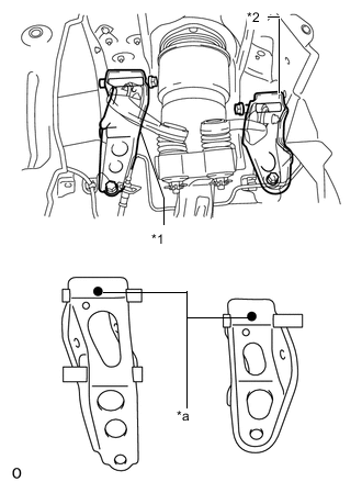
*1 Inner No. 1 Arm Attachment Plate *2 Inner No. 2 Arm Attachment Plate *a Distinguishing Color If the front suspension crossmember's left to right camber value is not as specified even though the camber and caster adjustment was performed, replace the No. 1 arm attachment plate inner and No. 2 arm attachment plate inner. Then perform the camber adjustment again.
Standard - No. 1 Arm Attachment Plate Inner No. 2 Arm Attachment Plate Inner Camber Angle Change Caster Angle Change - RH LH RH LH - - Arm Attachment Part No. and Distinguishing Color Standard Part 48614-50010
(Yellow)
48617-50010
(Yellow)
48614-50020
(White)
48617-50020
(White)
0 (Standard) 0 (Standard) +2 mm Part 48614-50030
(Pink)
48617-50030
(Pink)
48614-50050
(Blue)
48617-50050
(Blue)
+ 16.4' + 2.5' Tech Tips
For +2 mm parts, the upper arm installation hole is further toward the outside of the vehicle compared to standard parts.
-
-
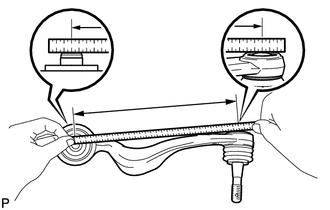
INSPECT FRONT SUSPENSION
-
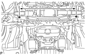
Inspect the front suspension member.
-
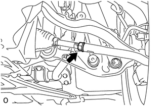
Measure the dimension between the center of the installation bolts of the front No. 2 suspension lower arm.
Standard length 788.0 mm (2.58 ft.) If the result is not within the specification, replace the front suspension member.
-
-
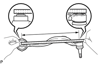
Inspect the front No. 1 suspension lower arm.
-
Remove the front No. 1 suspension lower arm.
-
Measure the dimension between the center of the front No. 1 suspension lower arm bush and the ball joint stud.
Standard length 385.5 mm (1.26 ft.) Tech Tips
If the dimension of the front lower suspension arm changes 2 mm (0.0787 in.), the camber will change approximately 15' (0.25°).
-
-
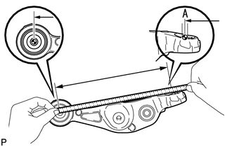
Inspect the front No. 2 suspension lower arm.
-
Remove the front No. 2 suspension lower arm.
-
Measure the dimension between the center of the front lower suspension arm bush and position A.
Standard length 315.6 mm (1.04 ft.) Tech Tips
If the dimension of the front lower suspension arm changes 2 mm (0.0787 in.), the camber will change approximately 15' (0.25°).
-
-
Inspect the front No. 1 suspension upper arm.
-
Remove the front No. 1 suspension upper arm.
-
Measure the dimension between the center of the front No. 1 suspension upper arm bush and the ball joint stud.
Standard length 235.8 mm (9.283 in.) Tech Tips
If the dimension of the front upper suspension arm changes 2 mm (0.0787 in.), the camber will change approximately 15' (0.25°).
-
-
Inspect the front No. 2 suspension upper arm.
-
Remove the front No. 2 suspension upper arm.
-
Measure the dimension between the center of the front No. 2 suspension upper arm bush and the ball joint stud.
Standard length 224.5 mm (8.839 in.) Tech Tips
If the dimension of the front upper suspension arm changes 2 mm (0.0787 in.), the camber will change approximately 15' (0.25°).
-
-
-
PLACE FRONT WHEELS FACING STRAIGHT AHEAD
-
REMOVE COWL TOP VENTILATOR LOUVER
-
PRECAUTION
Note
After turning the engine switch off, waiting time may be required before disconnecting the cable from the battery terminal. Therefore, make sure to read the disconnecting the cable from the battery terminal notice before proceeding with work.
-
DISCONNECT CABLE FROM NEGATIVE BATTERY TERMINAL
Note
-
When disconnecting the cable, some systems need to be initialized after the cable is reconnected.
-
Disconnect the cable from the negative battery terminal for 2 seconds or more.
-
-
CONNECT CABLE TO NEGATIVE BATTERY TERMINAL
-
INSTALL COWL TOP VENTILATOR LOUVER
-
PERFORM YAW RATE AND DECELERATION SENSOR ZERO POINT CALIBRATION
-
INITIALIZE ROTATION ANGLE SENSOR AND CALIBRATE TORQUE SENSOR ZERO POINT