THROTTLE BODY INSTALLATION
PROCEDURE
-
INSTALL THROTTLE BODY
-
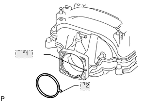
*1 Groove *2 Protrusion Install a new gasket to the intake manifold.
-
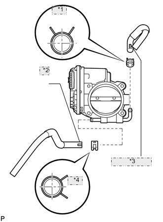
*1 Upper *2 Face Toward Front of Vehicle *3 Face Toward Upside of Vehicle *4 Front Connect the No. 4 water by-pass hose and No. 5 water by-pass hose to the throttle body.
Note
Position the claws of the clamps as shown in the illustration.
-
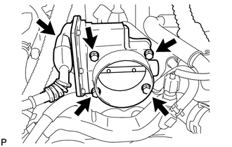
Install the throttle body with the 4 bolts.
- Torque:
- 10 N*m { 102 kgf*cm, 7 ft.*lbf }
-
Connect the throttle motor connector.
-
-
INSTALL INTAKE AIR CONNECTOR PIPE
-
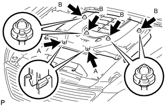
INSTALL NO. 1 AIR CLEANER INLET
-
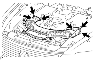
Align the holes with the connection areas labeled A, and attach the No. 1 air cleaner inlet.
-
Install the No. 1 air cleaner inlet with the 2 bolts.
- Torque:
- 5.0 N*m { 51 kgf*cm, 44 in.*lbf }
-
-
CONNECT CABLE TO NEGATIVE BATTERY TERMINAL
Note
When disconnecting the cable, some systems need to be initialized after the cable is reconnected Click here.
-
ADD ENGINE COOLANT
-
INSPECT FOR ENGINE COOLANT LEAK
-
PERFORM INITIALIZATION
Note
Perform the following procedure after replacing the ECM, throttle body assembly or any throttle body components. The following procedure should also be performed if the throttle body is cleaned.
-
Disconnect the EFI MAIN and ETCS fuses at the same time. Wait at least 60 seconds, and then reconnect the fuses.
-
Turn the engine switch on (IG) without operating the accelerator pedal.
Note
If the accelerator pedal is operated, perform the above steps again.
-
Connect the intelligent tester to the DLC3 and clear the DTCs Click here.
-
Start the engine and check that the MIL is not illuminated. After the engine is warmed up, check that the idle speed is within the specified range when the A/C is switched off.
Standard Condition Engine Idle Speed A/C switched off 700 to 800 rpm Note
-
Be sure to perform this step with all accessories off.
-
Make sure that the shift lever is in neutral.
-
-
Enter the following menus: Powertrain / Engine / Data List / All Data / Throttle Sensor Position. Sensor Output. Fully depress the accelerator pedal and check that the value is 60% or more.
-
Perform a road test and confirm that there are no abnormalities.
-
-
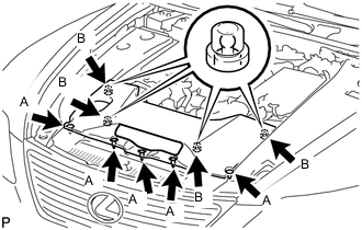
INSTALL AIR CLEANER INLET COVER SUB-ASSEMBLY
-
Attach the 4 clips B.
Note
-
Make sure the clips are attached securely.
-
Attaching the clips forcefully or hitting the top of the clips may damage them.
-
-
Install the air cleaner inlet cover sub-assembly with the 5 clips labeled A.
-
-
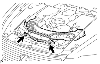
INSTALL V-BANK COVER SUB-ASSEMBLY
-
After sliding the cover from the vehicle front to the rear to attaching the 2 clips labeled A, attach the 4 clips labeled B and install the V-bank cover sub-assembly.
Note
-
Make sure the clips are attached securely.
-
Attaching the clips forcefully or hitting the top of the clips may damage them.
-
-
-
INSTALL NO. 1 ENGINE UNDER COVER
-
INSTALL COWL TOP VENTILATOR LOUVER RH